Shorted the throttle line - blew controller 5v rail

auraslip

10 MW
Joined
Mar 5, 2010
Messages
3,535
cause I broke it


I feel really dumb about this one.... My throttle died and I was double checking that it was the throttle by checking for 5v on the board, when BOOM. I had the multimeter setup to read AMP draw... Mistake 1 :(

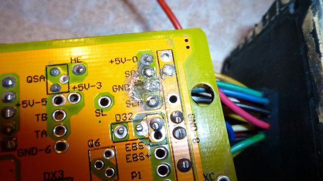
Knowing that it took a chunk out of the board I thought.."hrm well it says ground and it looks like it's supposed to be connected to ground." So I put a dab of solder from the throttle GRD to the ground trace on the circuit board.
You can see where I scrapped this off in an attempt to rectify the situation.

Anyways........

I hooked up everything, and everything looked good so I connected to the throttle green/blue SP line to the throttle 5v line. The motor jerked once and went dead.

Now it's not putting out 5v....

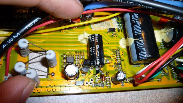
So this is the section that regulates 5v... everything is reading 3.7v. The 32ohm resistor I have my thumb on gets REALLY hot.

Everything after the fet is putting out nothing........ ack... I've broken like $350 worth of stuff over the last 3 days... first my signal bms... then this....... :(
 
If nobody else gets back to you on this, I'll check mine and see what I get where, but it's probably gonna be a couple days; dealing with getting my crazy sister out of the house, finally.
 
Based on the info here and in your other post:
http://www.endless-sphere.com/forums/viewtopic.php?p=378268#p378268
I'm gonna guess that the 7805 is toast, and it is dragging down the output of the hot resistor to that voltage, causing that heat by too much current.

Can you desolder the 7805? If so, you may find the resistor is no longer hot and the voltage at the input pad to 7805 is now more like 12V or higher.

If the 7805 is bad, then there are several places to get one out of electronics you may already have laying around as scrap.
 
Doc Bass had a similar hard to track down failure with similar symptoms. I'm sorry I don't know the thread, but it was about 9-10 months ago here in technical.
 
Doc Bass had a similar hard to track down failure with similar symptoms. I'm sorry I don't know the thread, but it was about 9-10 months ago here in technical.

I read through that and his final solution was to replace the MCU with one from a similar crystalyte unit... :/

If the 7805 is bad, then there are several places to get one out of electronics you may already have laying around as scrap.

I got one as a guess from "the shack" yesterday on a fluke. I'll swap it out really quick and let you know.
 
Well, at least that tells us the 7805 *was* bad, just that there is also something further down the line that died, too. Hopefully not the MCU (which also runs on that).
 
this thread has been RESURRECTED !

I made a little wiring harness to hook the controller up to my meanwell to try to get er' thing up and running again without having to pester lyen.


I found two things.

1: the zener diode in4744a appears to be open. With the multi-meter it seems to be infinite resistance from both ends.
2: One of the two transistors is putting out zero voltage. Where one is putting out 3.3v - the other is putting out zero.

Does anyone know what this portion of the board does anyways? It could be just a voltage divider and then a voltage regulator right? What's all this stuff in between?
What's the zener diode do? Is this some sort of voltage stabilisation system?
 
Check if you have +12 or so volts on the board. I think these guys regulate the 12 down to 5 with the LM7805. Also can you reconstruct the event so that we can back trace the overstress. The meter was on amps and you connected it between what and what? The blown copper shows more than just the 5v bus going to ground, I think.

See if this schematic matches up with what you see on your circuit board:


This schematic was snagged from "someone" on this board. Sorry for the lack of credit, I didn't link it to the author in my archive files.
 
Thanks moose - the lm7805 will operate between 9v-20v or something IRRC....

I hope this picture makes sense...

I think what happened was I had a probe in the throttle positive connector and I touched it to ground on the board.
 
I edited the above post and added a schematic for your consideration. If it matches, it should help in troubleshooting tremendously.
 
Thanks so much for the schematic!
Everything seems to match up...

Discrepancies in the comparator circuit, but that's because it traces to the 12v and 5v lines and I don't know where those are or come from. Not really sure how the comparator is supposed to work.
Wish I could "shotgun" and replace thay whole portion of the board.
 
Ok, take it a step at a time. Trace through the schematic and take voltage readings. Write them on a print of the schematic, take a picture of it and post it. We will do what we can to help.

The comparator is "toggling" the power through the three 1.5 K resistors that are paralleled. It is a poor mans voltage regulator. They use the 5 volt divided down as a reference voltage. When the 12 volt rail gets above the threshold it turns off Q1 which turns off Q2. We would call this a "bang bang" regulator in the lab.

Does your voltmeter have a diode check function? If so pull Q1 and Q2 and check for proper function of the NPN and the PNP function. Check C3 and D0 for shorts.
 
Ok I think I'm getting it now...

Pulled C3 (tested open), D0 (tested open), Q1 (tested good), and Q2 (tested bad).

D0 (in4744a) and Q2(mpsa93) will not pass current with the diode test.

So I guess I'll order those two parts and cross my fingers. Thanks for the help once again dave.
 
Your more than welcome. Post back any more problems and all of us will do our best.

If Q2 is cooked that would be a high probability possible. If the hot resistors were R11,R12, R13 perhaps labeled R33 we are getting more probable, particularly if R1 R2 R3 are ice cold.

Good luck with the repair!
 
I finally got and replaced Q2 and D0

Still doing 3.8v...

On the upside I think I understand how this "bang bang" works!

It seems like both Q1 and Q2 are off. Which means the switched series resistors are off. These turn off when voltage rises above 12v and drag it down...to 3.8v apparently. These need to be on!
I've tested the comperator and I think this is where the problem is... it's not getting 5v at it's VCC because it gets that from the lm7805 which can't run because it's not getting 12v because the switched series resistors can't turn on.

It's a chicken in the egg situation... there must be something I don't understand yet.
 
Let's see if we can help with the topology. Let's start simply. Q1 and Q2 are off. The flow of current is into Vcc-L then through the reverse polarity protection diode DS1. RS11, RS12 and RS33 are dropping the current for the baseline load at battery max voltage. The voltage drop across this resistor string is delta V = I *3000 D0 protects against over voltage as the 15 volt zener protection diode. Now some voltage between about 8 and 15 volts gets into the LM7805 and gets reduced to our 5 volt rail. Everything works... sort of. We want this quiescent condition to be high enough for the comparator to work.

The current through the string RS11,12,33 should be enough to power up the comparator. Now it compares, and turns on Q1 and Q2 to supply current through the paralleled R1, R2 and R3. The voltage starts to rise on the 12 volt rail, and feeds the inverting feedback on the comparator. I didn't do the math on the resistive dividers to see where things switch.

Hope this helps a little more. I am wondering if you have some silicon shorted. Can you measure the "housekeeping" current draw? What is the controller drawing with no motor connected.
 
Point of order... is rs11, 12, 13 (Just one 3k resistor on mine - RS1) a voltage divider? If so, what forms the second part of it?

If I'm understanding things correctly, before Q1, Q2, and the comparator even come into play the lm7805 should be seeing 8v-12v. Well their are minimal components between the lm7805 and vcc-l! Just rs1 in fact. I pulled and checked it and it's 3k ohms, so all good.

Since Q2 and Q1 are off and closed, there are just two diodes, two caps, and the voltage measurement system. Could these things be pulling the voltage down?
 
Easy one: RS11,12,13 is a "dropping resistor" and not a voltage divider per se.

Here is what I was thinking. You may have made this measurement already... but check the voltage drop across R1 R2 R3. If there is no voltage drop or delta V, then there is no current sourcing through this auxiliary dropping resistor. If there is a high delta V, then there is too much load on either the 12 volt rail or the LM7805. That "too much load" is from some shorted silicon on the board.

It may well be a problem with the comparator if there there is no delta V across R1 R2 R3.
 
Great news! Thanks to your help I figured it out!

You said the 5v line might be dragging down by a short, so I removed the lm7805 and sure enough the 12v rail came back up to 15v. Sure enough, resistance between ground and the 5v was 1 ohm! Apparently the diode DT1 in the picture bottom right was shorted. Removed it and re-installed the lm7805 and the 5v line came back on!

Woo... problem is... I can't read the markings on DT1 to replace it. I'm guessing it's some sort of over voltage protection zener diode?

Anyways, thanks so much for the help! You saved me like $100 and helped me learn a hell of a lot about electronics!
 
Back
Top