
jimmyhackers
10 kW
- Joined
- May 11, 2015
- Messages
- 609
yet another weird one here....
name kinda rounds up what i want.....i just need to know the "how to"
basically in my controller....and most as i assume, there's a shunt wire (3 in my case) that has a set resistance and from this it decides how many amps its going to send to my motor.
one of the wires seems to be nicked in several places. i guess this was a "factory" way of calibrating the controllers amp output.
googling ive seen many people get more amps/torque by simply beefing up these wire shunts with solder or thicker wire to give them more amperage.
this all seems to work soundly but its very..... uneasily reversible.
hence me wanting to find a way to change the controller output amperage at the flick of a switch.
so going back to that nicked shunt wire, if i solder on a wire to either side of the nicks and put a switch in parrallel......
will it work?
or is it not that simple?
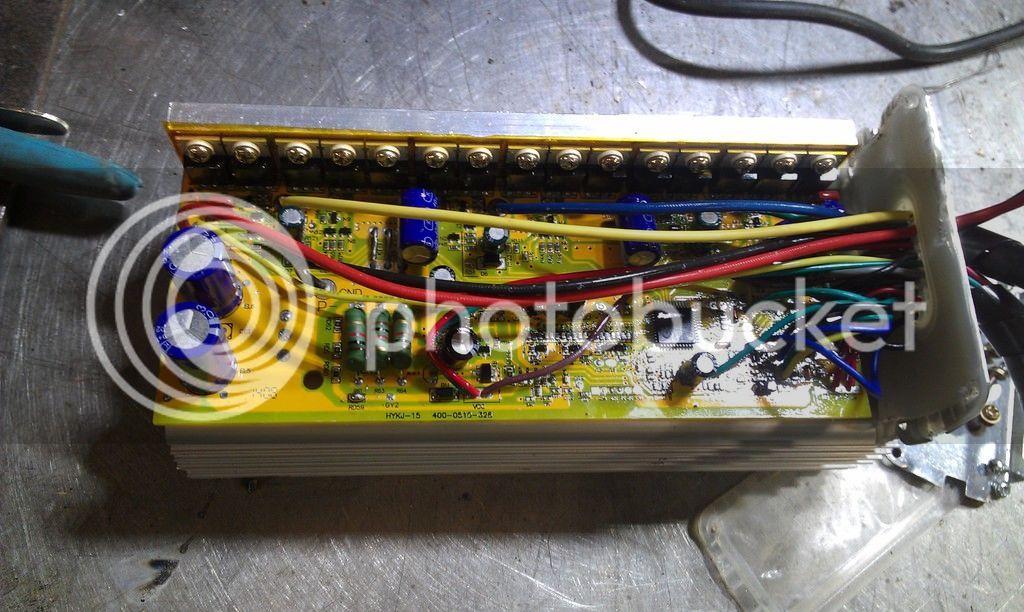
theres the guts.
thanks in advance for the help
jim