
Canonical source here: http://syonyk.blogspot.com/2015/07/bypassing-schwinn-tailwind-battery.html
=================
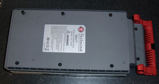
You might recall one of my previous posts about the Schwinn Tailwind battery pack. In a nutshell, it's a 24v, 4AH pack built of Toshiba SCiB lithium titanate cells. It's really a weird pack - but that's fine, because it's on a really weird bike. I did some analysis of it, but wasn't willing to hack it up as it wasn't my pack. So I fixed the glitch and bought the bike. It turns out, ebikes with bad battery packs aren't worth particularly much. I knew this, though.
Bad BMS - Bummer!
The problem with the pack I now own is a bad BMS (or a bricked BMS that won't allow anything to happen, because the batteries drained too far - same result). The pack won't charge, and it won't discharge. The BMS controls the normal charge and discharge ports with a set of power semiconductors of some form or another, and it's stubbornly refusing to run them.
Except... it does charge. The standard charge port for home use (8A charger - 2C rate... *blinks*) doesn't work, but the bulk charger (40A... 10C charge rate!!!) does, and I can charge the pack through that with an external power supply.
An inspection of the BMS shows that if I were to add a few wires to jumper current around, I could get pack voltage to the output - and get the normal charger port to charge the pack as well.
So, of course, this being an absolutely terrible idea, I set out to do it.
Lithium Titanate Chemistry
The only reason I'm considering this otherwise mostly idiotic idea is because the cells are lithium titanate. An extensive amount of research indicates that they're a very well behaved, safe chemistry that can actually be discharged fully without damage (unlike a lot of the other lithium chemistries). They're a low energy density chemistry as well, and I'm not too concerned about running them in light duty without a proper BMS. I wouldn't do this with other chemistries, though. Consider this a special case for a particularly exotic pack.
Don't Do This. Seriously, don't do this. And if you do, I'm not responsible.
This is a terrible idea, bypassing a BMS like I'm about to. You shouldn't do this. You definitely shouldn't get creative with my steps and do it better than I did. And if you do, I'm not responsible.
Seriously. This is battery hacking at a level that simply doesn't need to be done. Buy a 24v battery of some other type and hook it up instead. Don't do this.
... so read on to find out how to do this.
Getting to the BMS
To bypass the BMS, first, you must reach the BMS. This bit of wisdom was received from a sage on top of a mountain, though why a desert plant felt the need to tell me this, I'll never be quite sure.
The first step is to remove the 8 screws (6 Torx T20, two phillips) from the bottom of the case and remove the lower case.
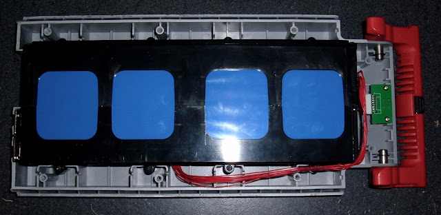
That done, marvel at the amount of wasted space in this shell, remove the 8 screws holding the actual battery in, disconnect the indicator light wire (it doesn't work anyway - bad BMS), and pull the battery pack out. The interesting stuff is, of course, on the bottom of it as you access things.
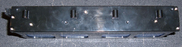
Once the pack is out, go ahead and remove the 7 screws on the side that protect the individual cell terminals. Once this is off, pack voltages are exposed, so be careful where you stick your tools. It's only a 24v pack, but it'll source some serious amps if you short it - don't do that.
Flip the pack over, and marvel at the more screws on the BMS cover. Four of them go into the plastic, and four mount the board. Remove all of them. Also remove the two screws on the front connecting the pack positive and negative terminals into the BMS. Be careful - they've got full pack voltage on them, so don't short them to anything! Or do, since you're not doing this anyway because it's a terrible idea.
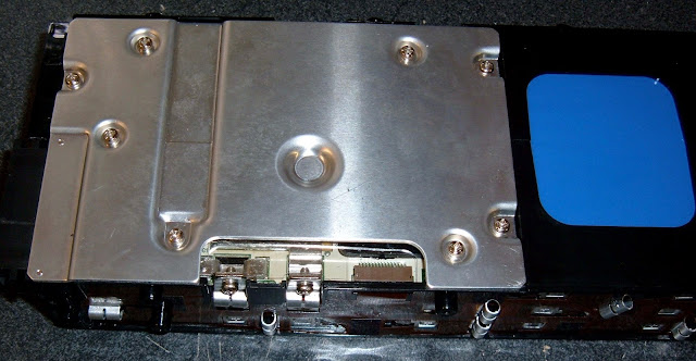
Once the 10 screws are out, you can pull the BMS board. Be careful of the ribbon cable on the front - that's the balancing cable. Pull it out gently before you remove the board. Once the board is clear, flip it over and remove the two small screws on either side of the charging connector, and the BMS should come free from the metal plate.
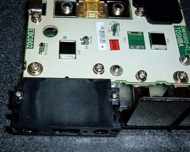
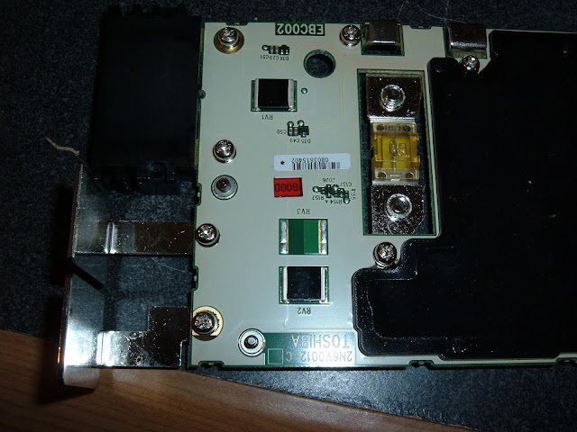
With the metal plate clear, you can see the business side of the BMS. There's some serious current carrying capability here - but I'm about to mess with it.
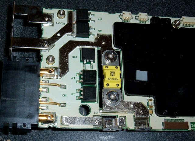
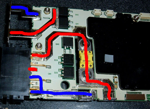
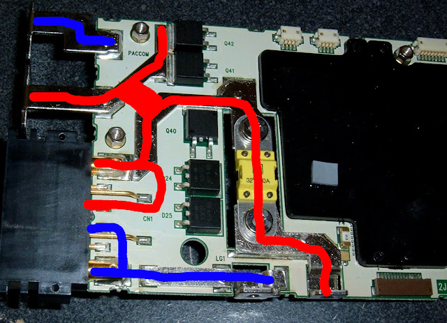
BMS Layout
Here's what the problem is. I've annotated the below diagram with lines, red for positive, blue for negative (and also, there's a common ground plane on the board so the negative lines are connected to each other - I've got 99 problems, but a split ground plane isn't one of them).
Without the BMS happy and functioning, there are three different positive islands that are causing my problems, because the two I care about (charging and discharging) are not connected to the third, which is the battery pack.
The two connections in the top left of the picture are the output connectors. They press against the spring loaded contacts in the bike mounting bracket, and transfer power to the bike. If they've got about 24v on them (plus or minus a good bit), the bike works. If they don't, it doesn't.
The lower charging connector is somewhat interesting (you can see more detail on it below). It's two different charging connectors in one. The outside two pins (the large ones) are for the high amperage charger. The inside pins are for the home charger. And then there are a few other pins that I assume are for diagnostic communication, or communication with the high amperage charger, but I sure can't find any details on them.
In any case, the inner pin that I'm interested in is not connected to anything unless the BMS connects it. Neither is the output. So this is what I need to fix.
Here's a better shot of the connector side of the BMS. The left two plates are the output plates - negative on the left, positive on the right. The righthand charging connector is really interesting. The outer sockets are for the high amperage charger - it's about 40A. The inner socket has two pins, and is for use with the home 8A charger. And I have no idea at all what the four other pins are - possibly contacts for the commercial charger, but that seems delicate. Maybe just for diagnostics. Nobody will tell me a damned thing about these packs, so I'm left to guessing. And doing terrible things to them in the hopes that someone at Toshiba will be horrified enough to tell me what I want to know.
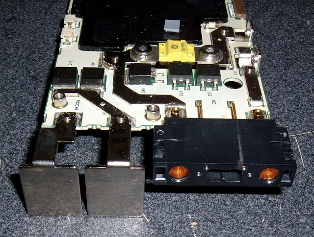
This is the other side of the board. This really is a "belt and suspenders" type board - the bolts go through the board... into where the traces (for some insane value of trace - these things are copper, coated with zinc or tin) are soldered onto the board. I really have no clue what went into this BMS, but I strongly suspect some engineer was very proud of it, figured it could comfortably drive a 50A load (it's got a 60A fuse), and was very sad when told it would drive a 250W bike (so about... 10A). Either that, or someone thought a safety factor of 6 was about right for this. I'd love the story sometime, if anyone happens to know. It's absurdly overbuilt, and I love it! It does make my hacking a bit harder, though...
The Goal
The end goal here is pretty simple: I'm going to fully bypass the BMS. I'm going to tie the charger connection, the battery terminals, and the discharge plates together, and they'll all be live, all the time, and this should just work.
Like this:
Things that do not work
I've found many ways to tie the rails together that do not work.
It turns out, these huge chunks of coated copper (WTF is coated copper doing on a 10A system???) are insanely good heatsinks, and my soldering irons are not capable of heating them very well. Certainly not to soldering temperatures.
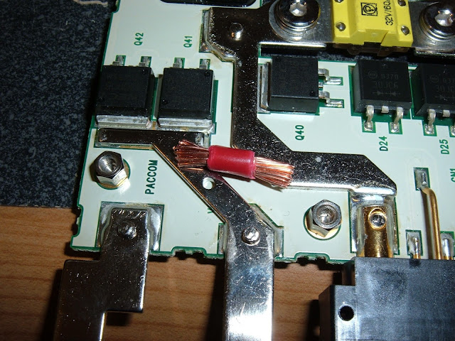
The first attempt was to use a chunk of copper wire, bridge the connections, and be done with the output side.
This didn't work. I could not get the bars to take solder. They simply would not get hot enough for the wire to stick. Not even close.
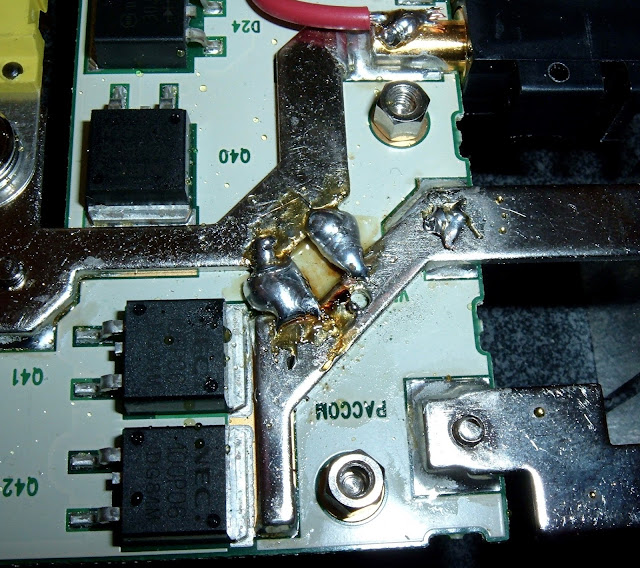
I also attempted to create some large solder bridges. This looked successful initially (I could get the solder to sort of stick to the edge of the traces), but a bit of fiddling with a screwdriver afterwards popped them right off - they weren't well attached at all, which means they won't flow much current, and I'd rather not have balls of solder floating around inside my battery pack. So that's out as well. Also, it's very ugly.
Another option that does not work is using circular terminals and wire. They're too thick (at least the ones I have). I'd need something very thin to fit the profile that I have available.
And yet another idea that does not work is trying to spot weld some nickel strip onto those traces. My spot welder (788+) is simply not powerful enough to do it. Though, to be fair, I didn't turn it all the way up. I've blown it up once and would rather not do it again.
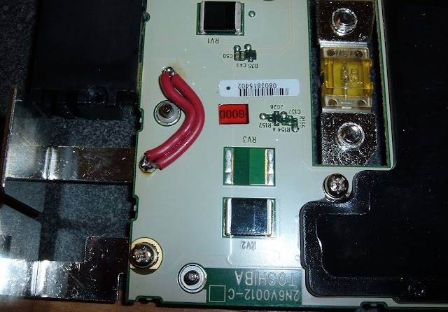
Something that actually works
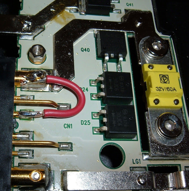
After some experimentation, I finally came up with something that works. I removed some of the unneeded bolts, and created a jumper between the charging port and the output port. It's still difficult to solder, but I was able to make it work. I went with two wires on the output side for somewhat increased current carrying capacity. This is a low power bike, so I'm not carrying many amps. I'd prefer to have done something more robust, but this is the best I could do with the tools available to me.
For the charging side, it was a lot easier. I was able to solder a single jumper wire and get it hooked up nicely. This should handle the charging current from the home charger just fine - especially since the pack charges up quickly and stops soaking as much current.
If you're doing this, of course use the largest wires you have available. This is a proof of concept.
Does it work? Yup!
The pack voltage is available on the outputs, and the charger works! Excellent!
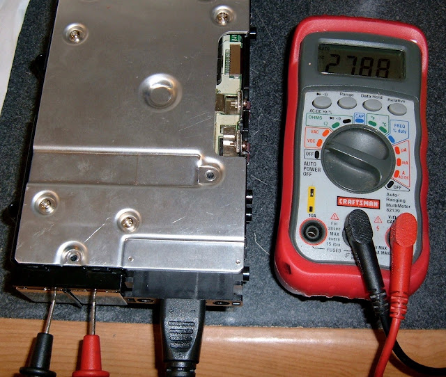
Does the bike work? Yes. It does.
"Runs & drives." For whatever limited value of running a Tailwind does.
What works? What doesn't work?
One of my biggest questions about this bypass is with regards to balancing. The cells should be balanced after charging, and I don't know if the BMS will do this or not in this weird bypassed state. So, data time. I rode it a bit, took some numbers, charged it, took some numbers, and then let it sit, and took some numbers.
Post-ride Pack Voltage
After a bit of a ride, this is what the pack looked like:
Total voltage: 23.40v
2.340v
2.340v
2.341v
2.341v
2.340v
2.340v
2.340v
2.340v
2.340v
2.340v
Well balanced, and nearly identical voltages. This is actually quite impressive for an older pack (the pack is 7 years old).
Let's see how it looks after a charge.
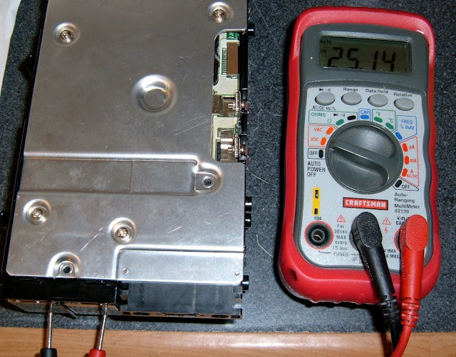
Charged Voltages
Pack voltage: 28.35
2.900v
2.845v
2.830v
2.800v
2.795v
2.797v
2.815v
2.805v
2.803v
2.806v
Oh. My. Wow. That's ugly. 0.1+v between the highest and lowest cells. This is not great, but maybe it works by bleeding off charge after topping off - I have no idea. The pack could be using magic for all I care. I do notice that the cells lose voltage quickly after a charge, so let's see how it looks after a few hours.
A few hours later...
Pack voltage:26.12
2.633
2.613
2.612
2.607
2.601
2.604
2.614
2.607
2.608
2.609
That's a lot better. Not perfect, but within reasonable ranges. So it's probably fine. I suspect the voltage/state-of-charge curve is nearly vertical at fully charged on these batteries, and I'm OK with a tiny bit of variance if it settles in nicely while discharging, which it does.
So: Should you do this if you have a Tailwind pack?
Well, this is pretty simple.
If the steps I outlined are somewhat confusing and sound a bit scary, absolutely not. This is not a trivial hack, and there's a lot that can go wrong.
If you're reading this, nodding, and occasionally saying things like, "Man, what an idiot. My 5kW soldering iron could totally solder onto those traces! And what's with that crappy solder job???" - yeah, you should probably consider doing this. It's not that difficult a job if you know what you're doing and have the right tools. Also, get some voltage into the cells before you plug the main charger in - I don't think it likes low voltages. I'd try to get about 2.5v per cell before using the main charger.
What's the best option for a Tailwind?
The best approach is probably to find another 24v battery, preferably one with a lot more capacity, and wire it in. I'll cover this in a future blog post at some point. This battery is just a weird bit of exotic oddness that makes no sense for an electric bike.
Will I do this for you?
Probably not. This is a quite ugly hack, and I'm not yet convinced it will hold for the long term. Sorry. But your local electronics geek might be willing to do it for you.
=================
You might recall one of my previous posts about the Schwinn Tailwind battery pack. In a nutshell, it's a 24v, 4AH pack built of Toshiba SCiB lithium titanate cells. It's really a weird pack - but that's fine, because it's on a really weird bike. I did some analysis of it, but wasn't willing to hack it up as it wasn't my pack. So I fixed the glitch and bought the bike. It turns out, ebikes with bad battery packs aren't worth particularly much. I knew this, though.
Bad BMS - Bummer!
The problem with the pack I now own is a bad BMS (or a bricked BMS that won't allow anything to happen, because the batteries drained too far - same result). The pack won't charge, and it won't discharge. The BMS controls the normal charge and discharge ports with a set of power semiconductors of some form or another, and it's stubbornly refusing to run them.
Except... it does charge. The standard charge port for home use (8A charger - 2C rate... *blinks*) doesn't work, but the bulk charger (40A... 10C charge rate!!!) does, and I can charge the pack through that with an external power supply.
An inspection of the BMS shows that if I were to add a few wires to jumper current around, I could get pack voltage to the output - and get the normal charger port to charge the pack as well.
So, of course, this being an absolutely terrible idea, I set out to do it.
Lithium Titanate Chemistry
The only reason I'm considering this otherwise mostly idiotic idea is because the cells are lithium titanate. An extensive amount of research indicates that they're a very well behaved, safe chemistry that can actually be discharged fully without damage (unlike a lot of the other lithium chemistries). They're a low energy density chemistry as well, and I'm not too concerned about running them in light duty without a proper BMS. I wouldn't do this with other chemistries, though. Consider this a special case for a particularly exotic pack.
Don't Do This. Seriously, don't do this. And if you do, I'm not responsible.
This is a terrible idea, bypassing a BMS like I'm about to. You shouldn't do this. You definitely shouldn't get creative with my steps and do it better than I did. And if you do, I'm not responsible.
Seriously. This is battery hacking at a level that simply doesn't need to be done. Buy a 24v battery of some other type and hook it up instead. Don't do this.
... so read on to find out how to do this.
Getting to the BMS
To bypass the BMS, first, you must reach the BMS. This bit of wisdom was received from a sage on top of a mountain, though why a desert plant felt the need to tell me this, I'll never be quite sure.
The first step is to remove the 8 screws (6 Torx T20, two phillips) from the bottom of the case and remove the lower case.
That done, marvel at the amount of wasted space in this shell, remove the 8 screws holding the actual battery in, disconnect the indicator light wire (it doesn't work anyway - bad BMS), and pull the battery pack out. The interesting stuff is, of course, on the bottom of it as you access things.
Once the pack is out, go ahead and remove the 7 screws on the side that protect the individual cell terminals. Once this is off, pack voltages are exposed, so be careful where you stick your tools. It's only a 24v pack, but it'll source some serious amps if you short it - don't do that.
Flip the pack over, and marvel at the more screws on the BMS cover. Four of them go into the plastic, and four mount the board. Remove all of them. Also remove the two screws on the front connecting the pack positive and negative terminals into the BMS. Be careful - they've got full pack voltage on them, so don't short them to anything! Or do, since you're not doing this anyway because it's a terrible idea.
Once the 10 screws are out, you can pull the BMS board. Be careful of the ribbon cable on the front - that's the balancing cable. Pull it out gently before you remove the board. Once the board is clear, flip it over and remove the two small screws on either side of the charging connector, and the BMS should come free from the metal plate.
With the metal plate clear, you can see the business side of the BMS. There's some serious current carrying capability here - but I'm about to mess with it.
BMS Layout
Here's what the problem is. I've annotated the below diagram with lines, red for positive, blue for negative (and also, there's a common ground plane on the board so the negative lines are connected to each other - I've got 99 problems, but a split ground plane isn't one of them).
Without the BMS happy and functioning, there are three different positive islands that are causing my problems, because the two I care about (charging and discharging) are not connected to the third, which is the battery pack.
The two connections in the top left of the picture are the output connectors. They press against the spring loaded contacts in the bike mounting bracket, and transfer power to the bike. If they've got about 24v on them (plus or minus a good bit), the bike works. If they don't, it doesn't.
The lower charging connector is somewhat interesting (you can see more detail on it below). It's two different charging connectors in one. The outside two pins (the large ones) are for the high amperage charger. The inside pins are for the home charger. And then there are a few other pins that I assume are for diagnostic communication, or communication with the high amperage charger, but I sure can't find any details on them.
In any case, the inner pin that I'm interested in is not connected to anything unless the BMS connects it. Neither is the output. So this is what I need to fix.
Here's a better shot of the connector side of the BMS. The left two plates are the output plates - negative on the left, positive on the right. The righthand charging connector is really interesting. The outer sockets are for the high amperage charger - it's about 40A. The inner socket has two pins, and is for use with the home 8A charger. And I have no idea at all what the four other pins are - possibly contacts for the commercial charger, but that seems delicate. Maybe just for diagnostics. Nobody will tell me a damned thing about these packs, so I'm left to guessing. And doing terrible things to them in the hopes that someone at Toshiba will be horrified enough to tell me what I want to know.
This is the other side of the board. This really is a "belt and suspenders" type board - the bolts go through the board... into where the traces (for some insane value of trace - these things are copper, coated with zinc or tin) are soldered onto the board. I really have no clue what went into this BMS, but I strongly suspect some engineer was very proud of it, figured it could comfortably drive a 50A load (it's got a 60A fuse), and was very sad when told it would drive a 250W bike (so about... 10A). Either that, or someone thought a safety factor of 6 was about right for this. I'd love the story sometime, if anyone happens to know. It's absurdly overbuilt, and I love it! It does make my hacking a bit harder, though...
The Goal
The end goal here is pretty simple: I'm going to fully bypass the BMS. I'm going to tie the charger connection, the battery terminals, and the discharge plates together, and they'll all be live, all the time, and this should just work.
Like this:
Things that do not work
I've found many ways to tie the rails together that do not work.
It turns out, these huge chunks of coated copper (WTF is coated copper doing on a 10A system???) are insanely good heatsinks, and my soldering irons are not capable of heating them very well. Certainly not to soldering temperatures.
The first attempt was to use a chunk of copper wire, bridge the connections, and be done with the output side.
This didn't work. I could not get the bars to take solder. They simply would not get hot enough for the wire to stick. Not even close.
I also attempted to create some large solder bridges. This looked successful initially (I could get the solder to sort of stick to the edge of the traces), but a bit of fiddling with a screwdriver afterwards popped them right off - they weren't well attached at all, which means they won't flow much current, and I'd rather not have balls of solder floating around inside my battery pack. So that's out as well. Also, it's very ugly.
Another option that does not work is using circular terminals and wire. They're too thick (at least the ones I have). I'd need something very thin to fit the profile that I have available.
And yet another idea that does not work is trying to spot weld some nickel strip onto those traces. My spot welder (788+) is simply not powerful enough to do it. Though, to be fair, I didn't turn it all the way up. I've blown it up once and would rather not do it again.
Something that actually works
After some experimentation, I finally came up with something that works. I removed some of the unneeded bolts, and created a jumper between the charging port and the output port. It's still difficult to solder, but I was able to make it work. I went with two wires on the output side for somewhat increased current carrying capacity. This is a low power bike, so I'm not carrying many amps. I'd prefer to have done something more robust, but this is the best I could do with the tools available to me.
For the charging side, it was a lot easier. I was able to solder a single jumper wire and get it hooked up nicely. This should handle the charging current from the home charger just fine - especially since the pack charges up quickly and stops soaking as much current.
If you're doing this, of course use the largest wires you have available. This is a proof of concept.
Does it work? Yup!
The pack voltage is available on the outputs, and the charger works! Excellent!
Does the bike work? Yes. It does.
"Runs & drives." For whatever limited value of running a Tailwind does.
What works? What doesn't work?
One of my biggest questions about this bypass is with regards to balancing. The cells should be balanced after charging, and I don't know if the BMS will do this or not in this weird bypassed state. So, data time. I rode it a bit, took some numbers, charged it, took some numbers, and then let it sit, and took some numbers.
Post-ride Pack Voltage
After a bit of a ride, this is what the pack looked like:
Total voltage: 23.40v
2.340v
2.340v
2.341v
2.341v
2.340v
2.340v
2.340v
2.340v
2.340v
2.340v
Well balanced, and nearly identical voltages. This is actually quite impressive for an older pack (the pack is 7 years old).
Let's see how it looks after a charge.
Charged Voltages
Pack voltage: 28.35
2.900v
2.845v
2.830v
2.800v
2.795v
2.797v
2.815v
2.805v
2.803v
2.806v
Oh. My. Wow. That's ugly. 0.1+v between the highest and lowest cells. This is not great, but maybe it works by bleeding off charge after topping off - I have no idea. The pack could be using magic for all I care. I do notice that the cells lose voltage quickly after a charge, so let's see how it looks after a few hours.
A few hours later...
Pack voltage:26.12
2.633
2.613
2.612
2.607
2.601
2.604
2.614
2.607
2.608
2.609
That's a lot better. Not perfect, but within reasonable ranges. So it's probably fine. I suspect the voltage/state-of-charge curve is nearly vertical at fully charged on these batteries, and I'm OK with a tiny bit of variance if it settles in nicely while discharging, which it does.
So: Should you do this if you have a Tailwind pack?
Well, this is pretty simple.
If the steps I outlined are somewhat confusing and sound a bit scary, absolutely not. This is not a trivial hack, and there's a lot that can go wrong.
If you're reading this, nodding, and occasionally saying things like, "Man, what an idiot. My 5kW soldering iron could totally solder onto those traces! And what's with that crappy solder job???" - yeah, you should probably consider doing this. It's not that difficult a job if you know what you're doing and have the right tools. Also, get some voltage into the cells before you plug the main charger in - I don't think it likes low voltages. I'd try to get about 2.5v per cell before using the main charger.
What's the best option for a Tailwind?
The best approach is probably to find another 24v battery, preferably one with a lot more capacity, and wire it in. I'll cover this in a future blog post at some point. This battery is just a weird bit of exotic oddness that makes no sense for an electric bike.
Will I do this for you?
Probably not. This is a quite ugly hack, and I'm not yet convinced it will hold for the long term. Sorry. But your local electronics geek might be willing to do it for you.


")