• Howdy! we're looking for donations to finish custom knowledgebase software for this forum. Please see our Funding drive thread

Solarcar power slide "now with fairing" but no solar, justEV

F&P

100 mW
Joined
Nov 17, 2009
Messages
47
Location
Melbourne, Australia
Hi Guys,

:D :D Just got my infineon controller putting out 45A at 48V instead of 28Amps, and man it goes, even spins the rear wheel on corners while powering on in gravel. Will spin from take off but not with me in it, but very close, a decent amount of weight on the rear wheel also. Will take it on a big run soon.

See this nice power slide on youtube.

http://www.youtube.com/watch?v=Ux1gCSBocmc

Fairing and 4 x 90W solar panels to be added next.
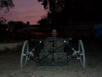
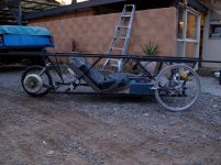
movember me in car.JPG

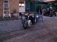
sideon view.JPG

rear view.JPG

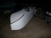
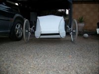
Pictures below also now with new corflute fairing that cost me about $30, will be adding a perpex roof soon and will next be making a singled wheeled trailer with 2 mounts to the EV and big enough to carry 4 x 80W solar panels and be very light, allum.
Will be adding some colours also and maybe even work logos etc to smarten it up.

First pic has a white painted line to show the shape of the proposed perpex roof approx.
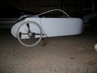
aa sidepaint.JPG

aarearfairing1.JPG

aafront1.JPG


F&P
Matt
 
I embedded your vid so folks don't have to open a new window to see it.

[youtube]Ux1gCSBocmc[/youtube]

Now let's see it burn out on pavement with you in it. :)
 
Very clever use of bicycle bottom brackets/cranks for the front steering/suspension setup too!

KiM
 
:D :D Thanks for noticing the pushbike bits etc to make up the front end suspension.
Yes really goes well and handles better than I imagined.

Wired up revesre on Sunday and WTF, it spins in backwards with me in it on our bituman carport, and has no soft start but is about 30% the speed compared to forward. Will post a reverse wheel spin video today with me in it.

Now this makes me think is it the hall sensor location or the controller limiting speed in reverse.
See picture, Red arrow present hall sensor location and blue arrows better location, your thoughts???

hall location.JPG

I feel it is the motors hall sensor location being closer the one coil than the other.
I will test it by reversing the phase wires and motor and controller etc to make it run backwards with controller in normal forwards motion and then compare in reverse on controller which will be forwards on motor, this should test if it is the motors hall location or controller.

I also made a big change to the body by deciding to make it a pure electic car and have the ability to tow a lightweight solar trailer when going on a long cruise. Now its a bit lighter and shorter and will look better with a fairing, will see in video of rear wheel spin in reverse.

F&P
 
Hi Guys,

Need to know what anyones thoughts are regarding the positioning of my current hall sensors. I mentioned it does have more torque in reverse and much less speed and still good torque in forwards but much faster.
Maybe I need somwhere in between like stabndard BLDC motors???

Will be wiring up the regen next, BX to groung I read??

Help please,

F&P
Matt
 
Wish i could help buddy i dont even know what a hall sensor looks like much less how to fit one ...
My 'expertise' stops at fabrication im afraid. I hope you get it sorted this is such a
resourceful build you and member 'amberwolf' have a bit in common with your
unique 're-purposing' of pre-owned parts....He is a bit of an electronics nut too he possibly could help you with your hall sensors...LiveforPhysics or Fechter would be others to PM if you have no response to the thread to (which im sure you will but in case....)

Shall follow your progress with interest i might learn something hopefully!

KiM

p.s i would like to use the F&P motors in a windmill setup i have the plans/destruction
on pc for converting them....when i get time i shall have a crack i have unlimited
supply to motors one of my best mates is a Washing Machine repair man haha..
 
Thank's Aussiejester,

will have to send out some PM to peolpe to see what tyey thing about the hall sensor location question.

Still yet to swap the phase wires, and try it in reverse mode which will be forwards with the wires wiotyched and will see whatb hepens hten.
i definatley has much more take off in reverse but no where near as fast. I'm sure it is the hall location and not the controller giving it more power as ity draws 47amps in forwards and reverse, so i feel this thing migt vene go better agin with the halls re-positioned.
Below is a diagram to show the doted lines being each stator laminate and the 0 being the corresponding hall locations.

Standard Present location ------ ------ ------ ------0 ------0 ------0 ------ ------ ------

Proposed Better location ------ ------ ------ ------ 0 ------ 0 ------ 0 ------ ------ ------

The F&P motors do have a differnt hall location layout compared to the bike hub motors i have seen, this also puzzles me?? with one hall sensor (the middle) located in the middle of a stator laminate??

Variable hall location might be the best option, to be looked at down the road.

The new fairning now turns some eyes when driving down the road, looks like an old open racing car in a strange way, can't wait to get some colour added.

F&P
Matt
 
F&P said:
Thank's Aussiejester,

will have to send out some PM to peolpe to see what tyey thing about the hall sensor location question.

You may have some 'callers' now mate, there has been a F&P thread started in the technical section i have posted a link there too your work log Matt

http://endless-sphere.com/forums/viewtopic.php?f=2&t=942

Best of luck hope you get it sorted ASAP

KiM
 
:) cool beans. looks like that motor could make some torque .

I am not a hall affect sensor expert . matter of fact this will be the first time i even play with hall sensors for my purpose (i thank methods he steered me straight) so others will most likely be able to help you more .

start by posting a thread in the ebike tech section or as AJ (good to see you again) has done, link to this one here.

first i would start by taking a look at the motor that controller was originally meant to spin and find out the degree of separation the hall sensors are setup at . the original purpose and control method of the motor has dictated the setup of the hall sensors and well you changed that a lil bit.

from your photos it looks to me like 3 of em at 20 degrees each making 60 . id bet the controller is looking for 90 or 120. if im right you havent seen the full potential of that setup even in forward.

good luck and ill be watching . lil self interest as it may help me , alot more out of curiosity .

side note : can you read a part # on the hall sensors and are they all the same ?

noob out.
 
Thanks for that info.
The controller I am using is the smart variety that can sense 60 or 120deg. Infineon 12fet, 45A running at 48V, voltage & Amps can be higher. I think mine is 60deg.

Yes should start a new thread on this F&P motor as i feel it can be a good DIY brushless type of project motor.
It does although require a lot of modifications including re-configuring the stator windings and removing the feritte mags and replacing with Neos. And there are many different configurations of windings from srtandard .8mm motor in series at 240V at about 300rpm and 1.5A to parallel at 40A / 12v at 800+/-rpm.

I will put some close up pics of hall sensor locations, but things are looking good after moving them about 2mm across and gaining noticable power.

Matt F&P
 
Matt...i was just looking at pics of the trike (full size) and if i am not mistaken
your using wheelchair hubs on the front? If so, I would HIGHLY recommend getting some heavy duty trike hubs on the front buddy, if they are wheel chair hubs i can tell you from personal experience they break very easily. I have broken EASILY half a dozen of those axles bouncing down stairs and off kerbs prior to going with the hollow threadless quick release Quickie axles. (which is another alternative you could look into they would fit those hubs) The issue i had with the wheelchair hubs is the axle breaks at the last thread on the axle, clean snap no bending they just let go. Could be a fun ride in the trike if it happens but also very dangerous one if on road...Thought i would bring it too your attention anywayz mate, disregard the above info if they aren't wheelchair hubs.

KiM
 
Were your wc hub pins the titanium ones, or regular steel/etc?

I have a set of 26" (-ish) wc wheels that have aluminum rims and hubs, stainless spokes, and steel sealed bearings, using a titanium QR pushbutton pin, which seats into a hardened steel tube bolted to a 1/4" aluminum plate that bolts to the heavy-gauge aluminum tubing on the wc. Do you think those would work as bike wheels?

FWIW, they have worked ok on my flatbed trailer so far, but it has not seen any abuse yet.

I also have some steel rimmed/hubbed sealed-bearing 20" wheels from a jogger's baby/grocery carriage, with hardened steel stub-axles and regular steel spokes. I'm not sure what they're weight-bearing ability is, as they look like they could take a lot more than the unit as a whole was rated for, since it was thin aluminum tubing with plastic joins, yet it was rated for over 100lbs on 3 wheels.

F&P: I am going to borrow a few of your clever repurposings, including the use of the BB/cranks for the pivots. I like that a LOT. :) If I could find one of those motors, I'd do that, too. But all the WM motors I've ever found in even newer scrapped WMs have been plain old induction motors, here in Phoenix.

The hall sensor issue I am not sure what to do about. I suspect the original placement was due to their controller design. Do those washers run thru an oscillation gearbox like induction motor washers do? Or do they directly reverse the motor for agitation cycles? If the latter, that is probably why they have the sensors where they do.

What I would do is move the sensors to wherever they would be in an equivalent-pole-count bike motor (or other BLDC motor intended for unidirectional operation). But mount them on a board that can be rotated around the circumference of the motor a few degrees, so that you can shift it mechanically when you need to run in reverse.

Alternately, use two sets of hall sensors--one for reverse and one for forward, each optimized in placement for your preferred way of operation in each mode, then run them thru open-collector-output AND gates with the F/*R signal. Meaning, each hall sensor would run into it's own single AND gate on one input, and the F/*R signal would run into the other input of every forward-function sensor's gate, and it's inverted version would run into the other input of every reverse-function sensor's gate.

The outputs of the gates would then go to their respective inputs on the controller, so that both A hall gates (F and R) are wired together and into the A phase sensor input, etc, with a pullup resistor to logic level on each pair.

Then only the hall signals from the currently selected mode would go to the controller.

If you're less electronically-inclined, the mechanical shifter method is probably easier. ;) For me, I'd probably stuff that one up, so I'd go with the electronic method, if I needed a reverse gear (I don't).
 
Thanks Kim and Amberwolf,

Amberwolf, yes please copy my front end design, it works a treat and costs nothing and is strong along with being able to last a long time.

Yes they are el-cheapo $20 new wheel chair wheels and the hollow axle version with a small amount of thread on the outside. I have welded them into place instead of the quick release system and they show no sings of bending yet.
I have pushed it hard on corners etc and gone over gutters and hit pot holes on gravel roads with no problem but the wheels are my main concern.
If the hubs themselves are strong enough, I would like to re-spoke them into a decent 24" mountain bike rim with heavier spokes if they are available???


frontend.JPG

This is an old stator below not being used, hence the rust and also has a burnt hall sensor.
I have plenty of different versions laying around.
As for reverse, I would be happier if it went ok in reverse and great in forwards, but it is the other way around. I am getting there as i have made up a cut down version of the hall sensor board which can be moved around. The only problem is that it runs well of the ground in any position really so i need to do a test run every time but a dyno would be the best option.
As a washing machine motor they are directly driven with no gears, thats the joy of them. Spin cycle might be forwards and wash might be in reverse.


Matt
F&P
 
I just had a half a page reply typed out went too hit enter and saw you have a reply Matt haha.. the hollow axles are the shot matey, in 9 years :: touch wood:: i havent bent or broken one and believe you me my chair gets quite a caining, from me and the mates hahaa. The hubs themselves are fine you wont have issues with them IMO... In future if you get some spare $$$ you could pick up some trike hubs from CyclesUS (chopersUS) they take a beefy 15mm axle, pretty much identical to what you have with excpetion to larger set of sealed bearings.

Shall be following your project with interest anywayz Matt im a sucker for DIY jobs and yours
intrigues me greatly :)

Best of luck..

KiM
 
See youtube link of the trike spinning the rear wheel in reverse and then forwards on our bituman driveway with a nobby BMX tyre. Will soon learn to attach a video correctly. Still has more go in revesre and will be adjusting that hall location any day now, and most likely set it up with variable hall timing via a simple cable.

http://www.youtube.com/watch?v=hFvnUxPbOTQ

Matt
F&P
 
Matt..hover your cursor over the [youtube] tags in the text editor it tlls you exactly how to embed videos its so simple. Everything AFTER the "=" sign in the youtube URL goes between the youtube tags thats it ..

[youtube]hFvnUxPbOTQ[/youtube]

KiM
 
Thanks Kim,

Will try it next time when posting a youtube link.
See link to the fisher&paykel thread, i have attched some close up pics of the shaft etc.

http://endless-sphere.com/forums/viewtopic.php?f=2&t=942&start=15

F&P
Matt
 
Back
Top