SOS! e-crazyman controller vs. Golden Motor Magic pie motor

avantgarden

100 mW
Joined
Feb 22, 2012
Messages
44
After the stock internal controller of my "Golden motor" magic pie motor died during an intensive regenerative braking I decided to follow a friends advice and I bought the 1500w 72v e-crazyman" controller:
http://www.ebay.com/itm/72V-1500W-brushless-controller-for-E-bike-scooter-/260847229409?pt=LH_DefaultDomain_0&hash=item3cbbb4d9e1
The seller (a very nice and intelligent guy) told me that he heard that some people did manage to pair this controller to the Magic pie but since he doesn't have such a motor he can't tell me the exact wiring.

Based on his advice I tried the following 2 combinations of controller/motor wirings:

1) Haul sensor cables : Yellow-Blue , Blue-Yellow, Green-Green, Red-Red, Black-Black.
Motor power cables: Yellow-Blue , Blue-Yellow, Green-Green
With this wiring the motor moves like a step motor. With no load (wheel spinning in midair) I got 15A of current.

2) Haul sensor cables : Yellow-Yellow ,Green-Blue, Blue-Green , Black-Black , Red-Red
Motor power cables: Yellow-Yellow ,Green-Blue, Blue-Green
With this wiring the motor makes farting sounds and doesn't even have the power to spin the wheel in midair.

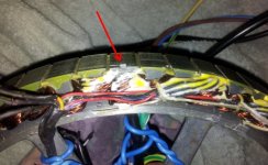
The attached picture shows the configuration I sent the controller. GUI replied "finished" so I assume the controller was properly set.

Does anyone have this combination of motor/controller and is willing to provide the exact wiring ?
Thanks.
 

Attachments

  • controller_setting.JPG
    controller_setting.JPG
    61.3 KB · Views: 2,362
According to a state table I just made, after cross connecting Yellow and blue and then cross connecting blue and yellow I was still left with a third option to try to cross connect Yellow and green:

3) Haul sensor cables : Yellow-Green , Green-Yellow, Blue-Blue, Red-Red, Black-Black.
Motor power cables: Yellow-Green , Green-Yellow, Blue-Blue
And so I did, only to find that with this wiring the motor moves like a step motor. With no load (wheel spinning in midair) I got 15A of current.

And just to make sure I didn't miss any chance, I also tried the unlikely fourth wiring possibility of no cross connection:
4) Haul sensor cables : Yellow-Yellow , Green-Green, Blue-Blue, Red-Red, Black-Black.
Motor power cables: Yellow-Yellow , Green-Green, Blue-Blue.
As I expected, this wiring produced no motor movement whatsoever.

Any suggestions ? Any measurements can be taken to make sure motor was not damaged ?
 
What I would do is first connect the halls colour to colour i.e y>y b>b g>g then try all 9 combinations of phase wires, chances are two of the 9 combinations will run the motor ( either forward or backwards ) pay close attention to the current drawn as if the combination is not correct high currents will flow, so just test wheel movement with 10% of throttle, only when you have the motor spinning and it sounds ok then wind the throttle up whilst watching the current ( you should not have no more than 3A at full throttle ) if the no load current is high then try another phase combination , if still no joy with a low no-load current after all nine phase combo's have been tried swap 2 of the hall sensor colours around and then re-test all 9 phase combos.
 
More data:

I disconnected the controller and measured resistance between the 3 power cables :
Green to blue : 0.3 ohm.
Green to yellow : 0.3 ohm.
Blue to yellow : 0.3 ohm.

Haul sensor measurements (Fluke is in Diode mode)

Fluke red pen to red haul sensor cable. Fluke black pen to Blue, Green and Yellow:
All gave 1.3 except Yellow

Fluke red pen to black haul sensor cable. Fluke black pen to Blue, Green and Yellow:
All gave 0.65 except Yellow

I'll open the motor and check if the yellow cable of the haul sensor was somehow connected...
 
The good news:
All the cabling I ran was perfect, including the cables to the "yellow haul sensor".

The bad news:
The "yellow" haul sensor is dead.

It fits a ~ 2mm x 3mm notch in the perimeter of the motor.
Does the Magic pie have standard haul sensors ?
 
Yes it does, standard honeywell ss41's will work fine, but the method you used to test them may have been wrong. Plug the controller in and check to see that the voltage is close to 5v between the hall red and black. Then measure between the signal leg and ground to each sensor and you should see an alternating voltage between 0 and 5 volts as you rotate the motor.
 
I confirmed this checking method with 2 friends of mine.
I followed your advice and ordered 3 of the ss41 (from Lyen).
The ones on my GM magic pie seem to be non honeywell ones. Not sure though...
Would you replace all of the 3 just to be on the safe side ?
 
I ordered 3 of the ss41. I'll have them all replaced.
Shipping from the US will take about 10 days to arrive and once they arrive I'll report my progress.
 
Here is closeup of the notch for the sensor.
David from GM got back to me today and told me that in addition to replacing the defected sensor I will also need to configure my external controller for a phase of 120 degrees.
 

Attachments

  • defected sensor.jpg
    defected sensor.jpg
    57 KB · Views: 2,279
I got the Honeywell SS41 hall sensors. Thanks Lyen.
I have some concerns regarding my motor though:

1. The sensors I got from Lyen are original Honywell SS41 sensors labeled "S41"
The 3 sensors I have on my motor (only one is defected) are labeled "40P 822". Not an original ?
2. The honywell is trapezoidal and the ones I have are rectangular
3. The honywell is a bit too big for the notch I have. I don't like the idea of machining the metal so close to the delicate motor wiring.
4. Assuming I'll resolve the notch space issue, Should I have all of them replaced to the honywell ?
5. How do I connect the honeywell sensor ? Assuming the sensor label is facing away from the motor axis how do I wire the red black & yellow cables ?
 
Finally I saw light in the darkness...My ebike is running !
Here is the process I had to go through + pictures:

Since the SS41 are slightly bigger than the crap I had on my GM motor I used tungsten carbide burr to widen the notches so the SS41 can fot into them.
In this picture you can see the result of the work with the tungsten carbide burr.

DANGER !!!
WHEN USING THE TUNGSTEN CARBIDE BURR, MAKE SURE YOU PROTECT THE MOTOR COILS WITH A FEW LAYERS OF THICK TAPE.
THE BURR HAS A TENDENCY TO RUN LOOSE AND CAN DESTROY YOUR MOTOR.
 
The next step is to fix the sensors to the notches with high quality epoxy putty.
The sensors must not be welded to the wires yet. Doing that will cause the sensors to move from a straight position. I learned it the hard way :(
 

Attachments

  • 20120412_225318_comp.jpg
    20120412_225318_comp.jpg
    361.8 KB · Views: 2,063
After sanding the surface where the rough epoxy putty mounts (Be careful not to sand the sensors !) I went and soldered all the wires to the sensors.
I made sure all motor measurements are correct:

Resistance between the 3 power cables :
Green to blue : 0.3 ohm.
Green to yellow : 0.3 ohm.
Blue to yellow : 0.3 ohm.

Haul sensor measurements (Fluke is in Diode mode)
Fluke red pen to red haul sensor cable. Fluke black pen to Blue, Green and Yellow:
All gave 1.8v

Fluke red pen to black haul sensor cable. Fluke black pen to Blue, Green and Yellow:
All gave 0.65v

I used heat shrink sleeves for each wire and covered all of the with a hot glue filled shrink sleeve to make sure nothing goes loose.
Sewing the whole deal is also recommended.
I also recommend to use a rigid cable like the blue one in the picture to secure the cables that connect to the stator.
If any of them will go loose there will be serious damage.

I also noticed that the motor cap on the disk brake side (second picture), has razor sharp edges that harm the cables on the axis anytime it's taken off.
Sanding it also a good idea.
 

Attachments

  • 20120413_155054_comp.jpg
    20120413_155054_comp.jpg
    281.3 KB · Views: 2,063
  • 20120412_230720_comp.jpg
    20120412_230720_comp.jpg
    317.7 KB · Views: 2,063
Now that the motor is done I assembled everything back and went on to connect the ecrazyman controller.
This is how the wires are connected...

Power cables:
Blue to Blue.
Green to Yellow.
Yellow to Green.

Sensor cables:
Blue to Blue.
Green to Yellow.
Yellow to Green.
Red to Red.
Black to Black.

Throttle and brakes are pretty straight forward...

Attached is the configuration I used.
 

Attachments

  • controller_setting.JPG
    controller_setting.JPG
    79.8 KB · Views: 1,058
The bike is running fine. The motor is quiet but I still have 3 concerns:

1. The old Golden Motor internal controller seemed to deliver more power.
Could it be that it was set to more than the values I set the ecrazyman controller (rated=22A; phase=56A) ?
2. I have regen enabled in software. When I go in a steep downhill:
- If I press the brake I get segmented braking. Is the controller cutting the too high current ?
- If I press no brake I seem to get a very weak but still noticeable engine braking.
With the old controller when brakes were not used the wheel was completely neutral. Will it help if I disable the regen with the software ?
3. During descents, when I suddenly close the throttle (no brakes applied at all) I sometimes get a segmented noise from the motor as if something is knocking there ...
 
Nice fix, dude!!

1) yes, 22A is a bit weak on a 26" wheel. The newer golden motor controllers put out 35A, not sure about the old, sorry.
2) this large diameter motor cogs like a mother, so it "engine brakes" pretty good. I'm not sure what you mean by segmented braking?
3) that's weird. spokes or torque arm problem maybe? does the same sound occur when you hit regen? could be that the throttle release puts the bike into regen mode with your settings..

avantgarden said:
The bike is running fine. The motor is quiet but I still have 3 concerns:

1. The old Golden Motor internal controller seemed to deliver more power.
Could it be that it was set to more than the values I set the ecrazyman controller (rated=22A; phase=56A) ?
2. I have regen enabled in software. When I go in a steep downhill:
- If I press the brake I get segmented braking. Is the controller cutting the too high current ?
- If I press no brake I seem to get a very weak but still noticeable engine braking.
With the old controller when brakes were not used the wheel was completely neutral. Will it help if I disable the regen with the software ?
3. During descents, when I suddenly close the throttle (no brakes applied at all) I sometimes get a segmented noise from the motor as if something is knocking there ...
 
regen is like that. It's either ON or OFF. you have a sensor in your brake line that is basically a switch.
 
"regen is like that. It's either ON or OFF. you have a sensor in your brake line that is basically a switch."
LOL !!! I try to be more clear :D

With the old internal GM controller
When regen was activated, by using one of the brakes, I was getting a long constant motor brake ( _______________ )

With the ecrazyman controller
When regen is activated, by using one of the brakes, I'm getting pulsating motor brake ( _ _ _ _ _ _ _ _ _ _ )
I'm wondering if the controller initiates these motor cuts to protect against too much current.
Not a bad idea considering the fact that what killed my internal GM controller was an aggressive regen when I was going down a 20% steep descent...
Nevertheless the pulses are very uncomfortable...
 
Oh! that's strange! could be the regen voltage limiter kicking in actually - yep, there is a limiter that tries to prevent your battery from being overcharged by the regen. If you have a particularly saggy battery that reverse sags pretty hard ( like the voltage jumps way up when you charge it ), this could be kicking in.

What voltage do you run, and what is your regen limit set at?

If it's very uncomfortable, your regen might be set high.... that could be exacerbating the problem too.

avantgarden said:
"regen is like that. It's either ON or OFF. you have a sensor in your brake line that is basically a switch."
LOL !!! I try to be more clear :D

With the old internal GM controller
When regen was activated, by using one of the brakes, I was getting a long constant motor brake ( _______________ )

With the ecrazyman controller
When regen is activated, by using one of the brakes, I'm getting pulsating motor brake ( _ _ _ _ _ _ _ _ _ _ )
I'm wondering if the controller initiates these motor cuts to protect against too much current.
Not a bad idea considering the fact that what killed my internal GM controller was an aggressive regen when I was going down a 20% steep descent...
Nevertheless the pulses are very uncomfortable...
 
These are the settings I'm using (attached screenshot)
Do you notice any regen current limit ?
 

Attachments

  • controller_setting.JPG
    controller_setting.JPG
    79.8 KB · Views: 1,057
I increased current setting to 26A and it's a rocket !
Power problem resolved !
I'm doing some experiments with regen settings. Stay tuned !
 
Now throttle regen problem is also resolved. I changed slip charge mode to 1 and now regen is totally disabled.
So the attached setting is the final one.
Thanks for your help, neptronix.

By the way...
I don't need to mention what a great product the ecrazyman controller is. Everybody knows that.
What I do need to mention is how great is the support I get from the guys selling this product. Especially Ge...
 

Attachments

  • controller_setting.JPG
    controller_setting.JPG
    84.2 KB · Views: 1,057
Back
Top