
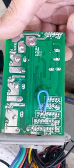
Greetings, I have already made the Shunt modification and it works perfectly, However, I cannot eliminate the speed limit having used the K and XS circuits. the now original maximum speed is 48 km/h with a full load. I attach photos of the controller. Thank you
You are using an out of date browser. It may not display this or other websites correctly.
You should upgrade or use an alternative browser.
You should upgrade or use an alternative browser.
Speed limit controller remove
- Thread starter filor6
- Start date


What is the speed with no load (wheel off the ground)?Greetings, I have already made the Shunt modification and it works perfectly, However, I cannot eliminate the speed limit having used the K and XS circuits. the now original maximum speed is 48 km/h with a full load. I attach photos of the controller. Thank you
Without K at GND the speed does not change (as original) The unmanned speed (with wheel raised) is 55 km/h. So the modification of the K was useless.What is the speed with no load (wheel off the ground)?
It’s not speed limited.Without K at GND the speed does not change (as original) The unmanned speed (with wheel raised) is 55 km/h. So the modification of the K was useless.
So is there a way to increase the top speed?It’s not speed limited.
The larger capacitor says 63 volts, the current battery is 48 volts. Should I then add a battery of just 4 volts in series?Run a higher voltage battery. I can’t read the caps with your pics, but you probably can run 52v on that controller.
No. There’s safety considerations when running batteries in series. If you’re asking the question, then you need to do a lot of reading to understand how to do so safely before attempting it.The larger capacitor says 63 volts, the current battery is 48 volts. Should I then add a battery of just 4 volts in series?
Besides raising the voltage, your other options would be a (programmable) controller that supports field weakening, or a motor with a faster winding.
docw009
10 MW
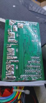
Probably was a 16A controller originally. Six MOSFET's in a tiny box. You're really pushing those transistors if you can do 48 kph under load with a noload of 55 km/hour, You should get a wattmeter to see what kind of battery current is flowing. Most will have a max current reading. I am guessing you're around 25A. Well, if the cobtroller melts, you can buy a bigger one,
.
.
Even though the board may indicate the possibility of a three speed switch, that doesn't necessarily mean that components installed on the board support that functionality. What components are mounted on the other side of the board, from the jumper you soldered in?It is strange however that the k2 circuit to GND does not give any effect. From what I understand it should thus reach 120 percent of the maximum speed. But there is no change. Maybe. In any case, thanks for your advice.

Probably was a 16A controller originally. Six MOSFET's in a tiny box. You're really pushing those transistors if you can do 48 kph under load with a noload of 55 km/hour, You should get a wattmeter to see what kind of battery current is flowing. Most will have a max current reading. I am guessing you're around 25A. Well, if the cobtroller melts, you can buy a bigger one,
.
Attachments

More volts.So is there a way to increase the top speed?
No.We did a lot of tests with the k1 and k2 circuits (speed 120%). IT DID NOT GIVE ANY RESULTS. One question I have is whether the K circuit should BE powered by (DC)? (as in the attached photo).
Remove the jumper and measure the voltage between your k1 and ground, and between k2 and ground with the controlleron. Both should have pull up resistors that should make k1 and k2 ~5v, if the circuitry for a three speed switch is present.
Thanks so much, I'll give this a try. Yes, my scooter has 3 speed gears on the display. If the 5v voltage was present, what should I connect?No.
Remove the jumper and measure the voltage between your k1 and ground, and between k2 and ground with the controlleron. Both should have pull up resistors that should make k1 and k2 ~5v, if the circuitry for a three speed switch is present.
Thank you
Hi, I measured the controller when turned on as your advice, k1 and k2 measure approximately 3.6 volts. So I think the K circuit is working... But it has no effect on speed. Maybe I should connect the jumper to another pin? Or on one of the 3 speed pins? (see photo above (SC SB SA).. Thanks for any advice.Thanks so much, I'll give this a try. Yes, my scooter has 3 speed gears on the display. If the 5v voltage was present, what should I connect?
Thank you
Hi, I measured the controller when turned on, k1 and k2 measure approximately 3.6 volts. So I think the K circuit works... But it has no effect on the speed by making the jumper to ground. Maybe I should connect the jumper to another pin? Or on one of the 3 speed pins? (see photo above (SC SB SA)?? .. Thanks for any advice.
Attachments


Similar threads
- Replies
- 10
- Views
- 477
- Replies
- 2
- Views
- 1,045
- Replies
- 1
- Views
- 315