Hello,
This is my first contribution to this forum.
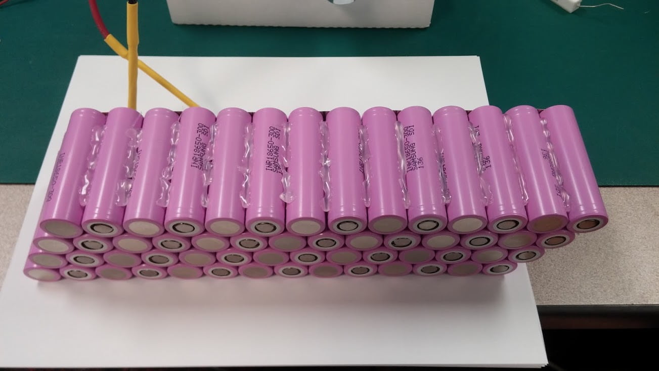
I've been working on my second ebike battery pack. This one is made with 18650 cells in a 14S4P configuration. I decided to make a capacitive discharge welder to properly assemble the pack since I already had most of the necessary components and I only had to spend $10 or so additional (the SCR). The pack is almost finished at this point, and I figured it would be good to write out some lessons learned for others who might want to do similar builds. I don't think anything in this build is unique, but there is definitely some things I could do better a second time... I've taken a lot of pictures so I could probably write out more stuff if there is interest.
Here's a few pictures of what's going on:
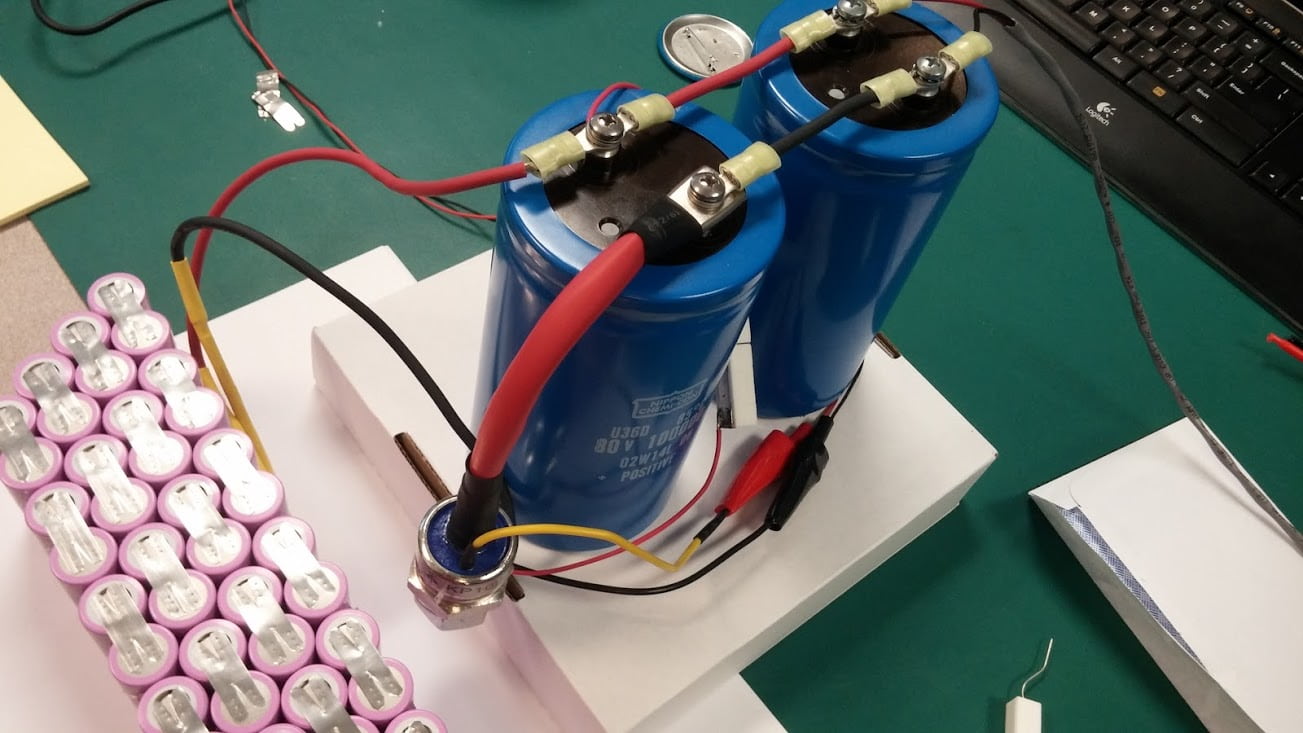
Welder:
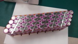
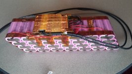
Battery:
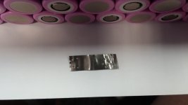
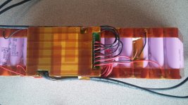
Welds:

So anyway, in no particular order, here's some things I recommend:
1. Don't use a car audio cap
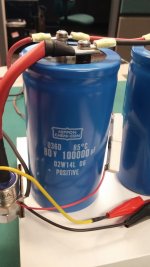
Some people have been successful with them, but I tried one and it was garbage. I recommend a real cap. I used this Nippon Chemi-Con electrolytic rated for 80V and 0.1F. I think it was about $50 when I got it years ago. Actually, I used two of them, but that's just because I had two sitting around. It was working fine with one.

2. Put a resistor across your probes
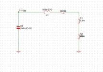
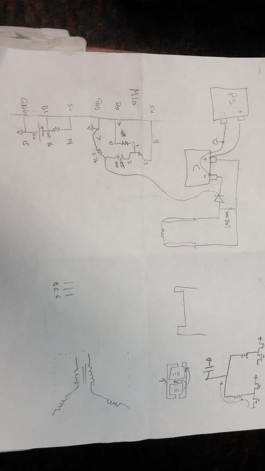
If you're going above ~20V to charge your caps and you're using an SCR like I did, then you should add a parallel resistor across your probes. You can see the resistor (the ceramic, high wattage) in the pictures above dangling between the caps. If you don't, your welder can/will discharge as soon as you touch your probes to the nickel strips even without you commanding a discharge (foot pedal in my case). It makes a huge pop and a lot of sparks (and is very exciting) and it damages your battery.
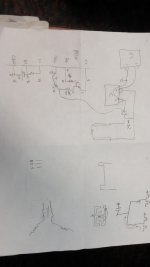
The issue is that the SCR is triggered by current on the gate, but can also be triggered by a high voltage slew between the anode and cathode. When you touch the probes to the metal, they are shorted and you have very quickly slewed the voltage and it will immediately trigger. To fix this, I just had to basically short the probes with a resistance which will keep them at approximately the same voltage when the probes are floating so there is no change when you short the probes together. Typically there will be no current going through this resistor since the probes make a lower impedance path, but I made them large power resistors to save them in case I triggered the welder without the probes making good contact in which case this resistor would take all the energy.
Here is a crude schematic. The resistor in question is the one that effectively shorts the probes.
3. Insulate your cells better before building
If I could go back, I would put another heat shrink sleeve on each cell before building. I don't want the insulation rubbing and the cans of the 18650 cells from adjacent rows to make contact. I would probably also but sheets of Kapton insulation between adjacent rows.
4. Nickel strips only
The first nickel spool I got was cheap and it was actually nickel plated steel. I didn't know to look out for this. If the spool is cheap, its probably nickel plated steel which is no good if your bike pulls good power.
5. Cut Vs in the strips
The welds are a lot stronger if you separate the weld dots by removing a strip of material. If you image search the commercial battery packs, you'll see that most have a notch taken out between the welds. It wasn't too hard to implement with a simple V cut as you can see in the above images. Remember you want to take all the energy stored in your cap and burn it at the interface of your nickel strip and your battery case; anywhere else is wasted and makes problems.
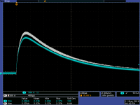
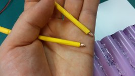
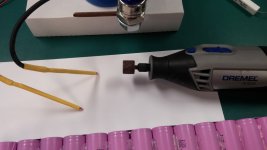
5. Keep the probe tips clean
The biggest contributor to making consistent welds was to clean the probe tips often and only touch new copper. The nickel actually melts onto the copper probes. You can see it if you look under a scope. This adds a lot of resistance to your probes and soon you're getting a lot of sparking and scarring. You want to make sure that the area of the probe tip that is touching the nickel strip is fresh.
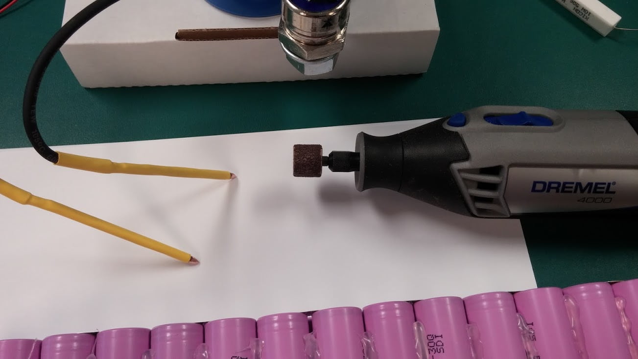
I got in the habit of only making two welds (4 dots) and then reconditioning the tips. I used a Dremel tool with a little sanding wheel to recondition the tips quickly. Also, I would make one weld then switch the probes between my hands which would basically force me to use a fresh section of the probe tip make the second weld. This welding schedule was tedious: one weld, switch probes, one weld, sand, repeat... but since I had no sparking once I started that schedule. Since this battery pack is a one-off, it was worth the time.
Here's a pic of the reconditioned (sanded) probe tips:

Happy battery pack making.
TaK
This is my first contribution to this forum.
I've been working on my second ebike battery pack. This one is made with 18650 cells in a 14S4P configuration. I decided to make a capacitive discharge welder to properly assemble the pack since I already had most of the necessary components and I only had to spend $10 or so additional (the SCR). The pack is almost finished at this point, and I figured it would be good to write out some lessons learned for others who might want to do similar builds. I don't think anything in this build is unique, but there is definitely some things I could do better a second time... I've taken a lot of pictures so I could probably write out more stuff if there is interest.
Here's a few pictures of what's going on:
Welder:
Battery:
Welds:
So anyway, in no particular order, here's some things I recommend:
1. Don't use a car audio cap
Some people have been successful with them, but I tried one and it was garbage. I recommend a real cap. I used this Nippon Chemi-Con electrolytic rated for 80V and 0.1F. I think it was about $50 when I got it years ago. Actually, I used two of them, but that's just because I had two sitting around. It was working fine with one.
2. Put a resistor across your probes
If you're going above ~20V to charge your caps and you're using an SCR like I did, then you should add a parallel resistor across your probes. You can see the resistor (the ceramic, high wattage) in the pictures above dangling between the caps. If you don't, your welder can/will discharge as soon as you touch your probes to the nickel strips even without you commanding a discharge (foot pedal in my case). It makes a huge pop and a lot of sparks (and is very exciting) and it damages your battery.
The issue is that the SCR is triggered by current on the gate, but can also be triggered by a high voltage slew between the anode and cathode. When you touch the probes to the metal, they are shorted and you have very quickly slewed the voltage and it will immediately trigger. To fix this, I just had to basically short the probes with a resistance which will keep them at approximately the same voltage when the probes are floating so there is no change when you short the probes together. Typically there will be no current going through this resistor since the probes make a lower impedance path, but I made them large power resistors to save them in case I triggered the welder without the probes making good contact in which case this resistor would take all the energy.
Here is a crude schematic. The resistor in question is the one that effectively shorts the probes.
3. Insulate your cells better before building
If I could go back, I would put another heat shrink sleeve on each cell before building. I don't want the insulation rubbing and the cans of the 18650 cells from adjacent rows to make contact. I would probably also but sheets of Kapton insulation between adjacent rows.
4. Nickel strips only
The first nickel spool I got was cheap and it was actually nickel plated steel. I didn't know to look out for this. If the spool is cheap, its probably nickel plated steel which is no good if your bike pulls good power.
5. Cut Vs in the strips
The welds are a lot stronger if you separate the weld dots by removing a strip of material. If you image search the commercial battery packs, you'll see that most have a notch taken out between the welds. It wasn't too hard to implement with a simple V cut as you can see in the above images. Remember you want to take all the energy stored in your cap and burn it at the interface of your nickel strip and your battery case; anywhere else is wasted and makes problems.
5. Keep the probe tips clean
The biggest contributor to making consistent welds was to clean the probe tips often and only touch new copper. The nickel actually melts onto the copper probes. You can see it if you look under a scope. This adds a lot of resistance to your probes and soon you're getting a lot of sparking and scarring. You want to make sure that the area of the probe tip that is touching the nickel strip is fresh.
I got in the habit of only making two welds (4 dots) and then reconditioning the tips. I used a Dremel tool with a little sanding wheel to recondition the tips quickly. Also, I would make one weld then switch the probes between my hands which would basically force me to use a fresh section of the probe tip make the second weld. This welding schedule was tedious: one weld, switch probes, one weld, sand, repeat... but since I had no sparking once I started that schedule. Since this battery pack is a one-off, it was worth the time.
Here's a pic of the reconditioned (sanded) probe tips:
Happy battery pack making.
TaK


") Am I right in thinking you use no discharge pulse-control?
Am I right in thinking you use no discharge pulse-control?