methods
1 GW
This build has been a roller-coaster of learning experiences. I never got around to posting up any details - but I get a few PM's and emails a week asking so here they are. Just so that we are clear - I dont really even want to sell these to "normal folk". They are just too powerful and complicated... not worth the trouble for us... but I do want to share the technical specification so that ya'll can make one for yourselves.
First: Credit to Steveo for the really nice 24 fet controller run he did before he (felt like he) got under-cut by Lyen. After thoroughly inspecting a sample of each - the amount of work that Steveo put into the controllers was impressive. If my recollection of history is correct he gave up the effort because he did not feel he could compete with Lyen on price - but in hind sight they were really two totally different products and I am sure Steveo's work would have passed the test of time. Much of my design picks off ideas from his production run. Lyen offers a very affordable controller - but it is not in the same league as that offered by Steveo.
Second: Credit to Matthew who did the lions share of the work on these controllers. Matthew's work is accurate and precise - which is critical for for reliable and repeatable production. All of the controllers were built at his shop using his tools and his guys. I could not be more happy with the results.
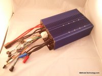
The theme of this controller was to be Ebikes.ca compatible. I wanted all of the folks who had previously purchased hubs or equipment from us or Justin to be able to upgrade to this with minimal fuss. I detest those short pigtails that terminate in bulky white Chines connectors as found on most controllers - so I had Keywin make up a custom set of wiring harnesses for us. He did an excellent job for a very reasonable price.
Features:
Rated for up to 24S Lipo
Dyno tested at 150A DC with 300A phase (controller does not even get warm before CroMotor melts into puddle)
IRFB4110 fets
100V Rubycon caps
6AWG Stranded trace reinforcements
6uF of 250V ultra low ESR ceramic caps spread across the rail (this is the secret sauce...)
Custom color-coded harness plug and play with Ebikes.ca equipment
Power switch on the box
Thermal protection on heat sink @ 70C
8AWG silicone phase wires
dual 10AWG silicone power wires
Blue anodized housing
Programmable via the awesome XPD software
Throw you over the bars regen power
3speed switch
CA V2 and V3 compatible
Cruise control
Torque throttle (available through CA-V3)
(that is all that I recall at the moment )
)
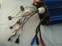
Connections
Throttle
Ebrake (for regen)
Cruise Control
3spd
Programming port
reverse
Power
Phase
Hall (extends out to 1 meter - slack pushed into the box)
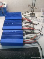
Build notes in order of importance:
CERAMIC CAPACITORS
Yea... all caps... that is how important it is. All those big electrolytic caps really do almost nothing to control the noise on the board. The real brunt of the work is done by those little m&m's on the rail - the tiny Mylar caps. Well.. that is not enough to win. To win - we need more ultra low ESR caps. The reason they are not on regular boards is because they are as expensive as hell... Buck each in small quantities.
250V
1.2uF
Ceramic
We build "surfboards" - small boards that hold 4-5 caps. These boards are wrapped in a super rubbery heat shrink and attached to the board in a modular way. This relieves them from the mechanical stresses that happen as all the 6AWG copper on the board expands and contracts.
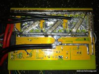
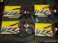
Here are all the things you should notice in that picture:
* 5 banks of caps. One holding up the left side of the rail, one holding up the right side of the rail, and one strapping each of the three phases - connected via the shortest possible path
* 4W Surface mount precision shunt mounted in parallel to the stock shunt. The important part is the kapton tape under the shunt - this insulates it from the via's underneath that are *not* fully masked
* The 6AWG stranded wire is only on the two main rails - not on every other little path. If you analyse the controller carefully you can see that the perpendicular paths carry only AC signals or low current signals. In reality - the heavy traces serve as more of a heat sink than anything... sucking the heat down out of those tiny TO-220 legs and keeping things sane in an insane environment.
* R12 mod - this is a must
* Power and Phase lines coming right off the bottom of the board. First - this shortens the path on the PCB and greatly simplifies assembly, inspection, and cable routing. Bringing the phase wires up between the heat sinks and the electrolitics is a fail - and running the power power line way up the side is also a fail. The ideal design landed the power wires right in the middle of the main positive rail - but that made for a crappy build so we compromised by moving it up to the side
* 6AWG on the phase landings too.... those pins need heat sinking as well!
* CA tap wires coming down and soldering in at the bottom of the board. Trying to jam two wires in a hole meant for one wire is fail - just bring the wire around the bottom and make a nice clean joint. Strain relieve it too up top! (as these will be the shortest wires and most abused)
* You cant see it - but CONFORMAL COAT your boards. It really is a MUST. Having a bunch of flux and solder balls and crap all over the place is how you fail. Fill a spray bottle with 91% alcohol and get out your moms toothbrush. Scrub that board like it owes you money until it shines like a chrome rim. It must be immaculate to win. Then - once it is perfectly clean - spray on some sort of conformal coating. This is like spacing out those TO-220 pins by a mile... the difference between having them sit next to each other at 100V 300A bare... and coated... are totally different worlds. It takes almost nothing to get a short circuit so do everything you can to avoid it.
Ok - that was a lot to see in one picture right?
You get the idea of the caps... I have already posted the information on where to find them etc. It totally screwed me and overnight every bit left on the shelves sold out and we got delayed on our build by months. If anyone wants those caps they can search my postings and find the link.
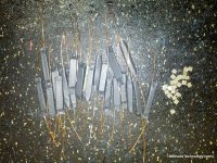
(shameless sales pitch) - we will be offering "surfboards" this spring in kit form. Small rectangular boards with the caps and leads already soldered on. This will be the ultimate upgrade to the otherwise stock controllers that dominate the market. Those looking to "go crazy" can solder the shunt, beef up the traces, and install 3-5 surfboards to help keep that crazy controller noise under control. You will see them once they are available.
The production units will be much prettier... purple board, clear shrink, sexy little things. You will want to put them in the band of your underwear and dance around like a fool once you touch them.
Ok - what was I doing?
Oh yea - sharing all the details of our design so that you can copy it for free
(Open to requests - no "trade secrets" here - we will tell you everything we know)
To make our end-cap gaskets we coat the end-caps with a think film of silicone. We then let it dry (that's the key...) Doing it this way gets you a good seal but also allows you to open the controller for service and inspection. If you assemble them wet it is like gluing them together (fail).
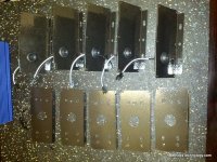
See how the end caps are connectorized? That is how you win. Forget all that crap about sliding the end cap through the extruded housing - yanking all the wires and getting white goop on everything. Just use a $0.30 connector and make it clean. Also pays off big-time during testing since you can then take a raw board (without endcap or housing) and wire it up to a testing station.
Speaking of testing - testing is everything. Here is how we check out a controller before first powering it up.
VISUAL INSPECTION:
* Visually inspect that there are no solder bridges - especially on the TO-220 pins and the TO-92 BJT pins that pop up in the middle of the phase pads. This careful visual inspection is CRITICAL since nobody has the time to do a point by point electrical test
ISOLATION TESTS:
We only use FLUKE brand products. A fluke meter will consistently give reliable and repeatable readings when measuring into an active circuit. An active circuit has all sorts of capacitance and stray voltages... these voltages will totally fool cheap DMM's and they will give you BAD DATA. Dont be a sucker - dont be fooled. We chased our ass for hours over a $50 DMM reading that was false.
Measure resistance between power and ground. Should be something big. If it is 10K then you have a problem. This batch of controllers shipped with a large 10K resistor strapped across the main input caps. This MUST be removed!!!
100V / 10Kohms = 10mA
You want a constant 10mA draw on your battery 24/7?
That will totally destroy your pack in a matter of days.
Ok - if there are any shorts between power and ground you fail - go back and fix what is broke.
Now you want to measure from ground to phase and phase to power
EDIT: One hour just passed - I am totally distracted now
Ground to phase you should see a clean 10kohms
Phase to power you can see anything - sometimes 10kohms and sometimes random readings - the stray voltages play a huge role here. Important thing to note is that if any of these read near 0ohms you have a short or blown mosfets
Next isolation needs to be tested on the heatsink - power, ground, and all three phases to the heat sink.
Ok - I am totally distracted now. A mad-man just called my house and started filling my ear full of all sorts of ideas for this years product line. Damn it is hard to stay focused. The new HVC/LVC true battery breaker and the cell level charging boards. Hmmm... ugh.
Yea - uh - so I suppose I am wasting time writing this since I have no intention of making any more of these If anyone has any questions about how we do it just ask and I will show and tell.
Over the last year or two I have devolved form a contributing member into somewhat of a hustling vendor. This disgusts me as my main goal has always been to just make the coolest stuff I can for myself, and share that design with everyone else. In that spirit - all should know that I harbor no secrets in my design or documentation and I wish to share all of it for free to anyone who asks.
Ok - I am going to go build the prototype for this years HVC/LVC breaker
So sweet... going to mount right to the battery and give true isolation of the battery for LVC or HVC. My main interest in the project is building 4S accessory packs for myself that I can use for jumping cars, powering cell phones, powering AC inverters, etc. I love the idea of knowing that there is no way to over-discharge them. Anyway - I am going to make one for myself then make 100 of them for sale. Hopefully it wont be a costly fail. I suspect it will be FTW.
-methods
First: Credit to Steveo for the really nice 24 fet controller run he did before he (felt like he) got under-cut by Lyen. After thoroughly inspecting a sample of each - the amount of work that Steveo put into the controllers was impressive. If my recollection of history is correct he gave up the effort because he did not feel he could compete with Lyen on price - but in hind sight they were really two totally different products and I am sure Steveo's work would have passed the test of time. Much of my design picks off ideas from his production run. Lyen offers a very affordable controller - but it is not in the same league as that offered by Steveo.
Second: Credit to Matthew who did the lions share of the work on these controllers. Matthew's work is accurate and precise - which is critical for for reliable and repeatable production. All of the controllers were built at his shop using his tools and his guys. I could not be more happy with the results.

The theme of this controller was to be Ebikes.ca compatible. I wanted all of the folks who had previously purchased hubs or equipment from us or Justin to be able to upgrade to this with minimal fuss. I detest those short pigtails that terminate in bulky white Chines connectors as found on most controllers - so I had Keywin make up a custom set of wiring harnesses for us. He did an excellent job for a very reasonable price.
Features:
Rated for up to 24S Lipo
Dyno tested at 150A DC with 300A phase (controller does not even get warm before CroMotor melts into puddle)
IRFB4110 fets
100V Rubycon caps
6AWG Stranded trace reinforcements
6uF of 250V ultra low ESR ceramic caps spread across the rail (this is the secret sauce...)
Custom color-coded harness plug and play with Ebikes.ca equipment
Power switch on the box
Thermal protection on heat sink @ 70C
8AWG silicone phase wires
dual 10AWG silicone power wires
Blue anodized housing
Programmable via the awesome XPD software
Throw you over the bars regen power
3speed switch
CA V2 and V3 compatible
Cruise control
Torque throttle (available through CA-V3)
(that is all that I recall at the moment

Connections
Throttle
Ebrake (for regen)
Cruise Control
3spd
Programming port
reverse
Power
Phase
Hall (extends out to 1 meter - slack pushed into the box)

Build notes in order of importance:
CERAMIC CAPACITORS
Yea... all caps... that is how important it is. All those big electrolytic caps really do almost nothing to control the noise on the board. The real brunt of the work is done by those little m&m's on the rail - the tiny Mylar caps. Well.. that is not enough to win. To win - we need more ultra low ESR caps. The reason they are not on regular boards is because they are as expensive as hell... Buck each in small quantities.
250V
1.2uF
Ceramic
We build "surfboards" - small boards that hold 4-5 caps. These boards are wrapped in a super rubbery heat shrink and attached to the board in a modular way. This relieves them from the mechanical stresses that happen as all the 6AWG copper on the board expands and contracts.

Here are all the things you should notice in that picture:
* 5 banks of caps. One holding up the left side of the rail, one holding up the right side of the rail, and one strapping each of the three phases - connected via the shortest possible path
* 4W Surface mount precision shunt mounted in parallel to the stock shunt. The important part is the kapton tape under the shunt - this insulates it from the via's underneath that are *not* fully masked
* The 6AWG stranded wire is only on the two main rails - not on every other little path. If you analyse the controller carefully you can see that the perpendicular paths carry only AC signals or low current signals. In reality - the heavy traces serve as more of a heat sink than anything... sucking the heat down out of those tiny TO-220 legs and keeping things sane in an insane environment.
* R12 mod - this is a must
* Power and Phase lines coming right off the bottom of the board. First - this shortens the path on the PCB and greatly simplifies assembly, inspection, and cable routing. Bringing the phase wires up between the heat sinks and the electrolitics is a fail - and running the power power line way up the side is also a fail. The ideal design landed the power wires right in the middle of the main positive rail - but that made for a crappy build so we compromised by moving it up to the side
* 6AWG on the phase landings too.... those pins need heat sinking as well!
* CA tap wires coming down and soldering in at the bottom of the board. Trying to jam two wires in a hole meant for one wire is fail - just bring the wire around the bottom and make a nice clean joint. Strain relieve it too up top! (as these will be the shortest wires and most abused)
* You cant see it - but CONFORMAL COAT your boards. It really is a MUST. Having a bunch of flux and solder balls and crap all over the place is how you fail. Fill a spray bottle with 91% alcohol and get out your moms toothbrush. Scrub that board like it owes you money until it shines like a chrome rim. It must be immaculate to win. Then - once it is perfectly clean - spray on some sort of conformal coating. This is like spacing out those TO-220 pins by a mile... the difference between having them sit next to each other at 100V 300A bare... and coated... are totally different worlds. It takes almost nothing to get a short circuit so do everything you can to avoid it.
Ok - that was a lot to see in one picture right?
You get the idea of the caps... I have already posted the information on where to find them etc. It totally screwed me and overnight every bit left on the shelves sold out and we got delayed on our build by months. If anyone wants those caps they can search my postings and find the link.


(shameless sales pitch) - we will be offering "surfboards" this spring in kit form. Small rectangular boards with the caps and leads already soldered on. This will be the ultimate upgrade to the otherwise stock controllers that dominate the market. Those looking to "go crazy" can solder the shunt, beef up the traces, and install 3-5 surfboards to help keep that crazy controller noise under control. You will see them once they are available.
The production units will be much prettier... purple board, clear shrink, sexy little things. You will want to put them in the band of your underwear and dance around like a fool once you touch them.
Ok - what was I doing?
Oh yea - sharing all the details of our design so that you can copy it for free
(Open to requests - no "trade secrets" here - we will tell you everything we know)
To make our end-cap gaskets we coat the end-caps with a think film of silicone. We then let it dry (that's the key...) Doing it this way gets you a good seal but also allows you to open the controller for service and inspection. If you assemble them wet it is like gluing them together (fail).

See how the end caps are connectorized? That is how you win. Forget all that crap about sliding the end cap through the extruded housing - yanking all the wires and getting white goop on everything. Just use a $0.30 connector and make it clean. Also pays off big-time during testing since you can then take a raw board (without endcap or housing) and wire it up to a testing station.
Speaking of testing - testing is everything. Here is how we check out a controller before first powering it up.
VISUAL INSPECTION:
* Visually inspect that there are no solder bridges - especially on the TO-220 pins and the TO-92 BJT pins that pop up in the middle of the phase pads. This careful visual inspection is CRITICAL since nobody has the time to do a point by point electrical test
ISOLATION TESTS:
We only use FLUKE brand products. A fluke meter will consistently give reliable and repeatable readings when measuring into an active circuit. An active circuit has all sorts of capacitance and stray voltages... these voltages will totally fool cheap DMM's and they will give you BAD DATA. Dont be a sucker - dont be fooled. We chased our ass for hours over a $50 DMM reading that was false.
Measure resistance between power and ground. Should be something big. If it is 10K then you have a problem. This batch of controllers shipped with a large 10K resistor strapped across the main input caps. This MUST be removed!!!
100V / 10Kohms = 10mA
You want a constant 10mA draw on your battery 24/7?
That will totally destroy your pack in a matter of days.
Ok - if there are any shorts between power and ground you fail - go back and fix what is broke.
Now you want to measure from ground to phase and phase to power
EDIT: One hour just passed - I am totally distracted now
Ground to phase you should see a clean 10kohms
Phase to power you can see anything - sometimes 10kohms and sometimes random readings - the stray voltages play a huge role here. Important thing to note is that if any of these read near 0ohms you have a short or blown mosfets
Next isolation needs to be tested on the heatsink - power, ground, and all three phases to the heat sink.
Ok - I am totally distracted now. A mad-man just called my house and started filling my ear full of all sorts of ideas for this years product line. Damn it is hard to stay focused. The new HVC/LVC true battery breaker and the cell level charging boards. Hmmm... ugh.
Yea - uh - so I suppose I am wasting time writing this since I have no intention of making any more of these
Over the last year or two I have devolved form a contributing member into somewhat of a hustling vendor. This disgusts me as my main goal has always been to just make the coolest stuff I can for myself, and share that design with everyone else. In that spirit - all should know that I harbor no secrets in my design or documentation and I wish to share all of it for free to anyone who asks.
Ok - I am going to go build the prototype for this years HVC/LVC breaker
So sweet... going to mount right to the battery and give true isolation of the battery for LVC or HVC. My main interest in the project is building 4S accessory packs for myself that I can use for jumping cars, powering cell phones, powering AC inverters, etc. I love the idea of knowing that there is no way to over-discharge them. Anyway - I am going to make one for myself then make 100 of them for sale. Hopefully it wont be a costly fail. I suspect it will be FTW.
-methods

