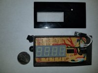
battman
1 W
Overview
This project provides reliable and scalable monitoring of temperatures through one or more digital sensors with results shown on a 4 digit LED display. The initial implementation has been used to monitor temperature at 12 points within an existing battery pack.

Usage
On power up, the sensors are initialized to 9 bit resolution (if not set to this already) and the number of attached sensors is read.
Switch SW1 is used to select between two display modes, default to mode B:
A. Read the temperature of all sensors and display the sequence number and temperature of the sensor with the highest temperature reading. The refresh rate for this value is 0.1 seconds * number of attached sensors.
B. Cycle over each sensor, read and display its temperature for 0.6 seconds.
The first two digits of the display show sensor number and the second two display temperature in degrees celcius with the display value clamped to 0 or 99 if the temperature exceeds those limits.
The sequence number of a sensor is determined by the unique 64-bit serial code stored in its ROM and is not configurable in this project implementation, although see the Enhancements section below for how the sequence could be made configurable.
Design Decisions
The digital temperature sensor DS18B20 was chosen for the following reasons:
Digital sensors certainly cost a lot more than analog sensors, but the benefits listed above were considered to far outweigh the extra cost. Shop around for the DS18B20 - its cost varies widely online. If 2oC accuracy is sufficient and it can be found at a good price, the DS1822+T&R should work as a drop-in alternative.
The combination of a low pin count microcontroller, the Microchip PIC16F15313, plus a display driver chip, the Maxim MAX6958, was chosen in preference to a single high pin count microcontroller performing both duties for the following reasons:
The value of 2.2K pullup resistor between the sensor DQ and V+ lines could possibly be increased. Initial testing was performed with a 4.7K resistor but instability was seen with more than 8 sensors at the higher resistance.
Schematic

The perfboard layout for the components is shown in this PDF:
View attachment temperature_monitor_perfboard.pdf
BOM
The BOM is just for the electronic components with a single BS18B20 sensor and does not include the perfboard, SPST momentary N.O. switch or connectors.
View attachment temperature_monitor_bom.csv
Source Code
https://github.com/barrongreig/TemperatureMonitor
Enhancements
A couple of useful enhancements to this project could be:
This project provides reliable and scalable monitoring of temperatures through one or more digital sensors with results shown on a 4 digit LED display. The initial implementation has been used to monitor temperature at 12 points within an existing battery pack.

Usage
On power up, the sensors are initialized to 9 bit resolution (if not set to this already) and the number of attached sensors is read.
Switch SW1 is used to select between two display modes, default to mode B:
A. Read the temperature of all sensors and display the sequence number and temperature of the sensor with the highest temperature reading. The refresh rate for this value is 0.1 seconds * number of attached sensors.
B. Cycle over each sensor, read and display its temperature for 0.6 seconds.
The first two digits of the display show sensor number and the second two display temperature in degrees celcius with the display value clamped to 0 or 99 if the temperature exceeds those limits.
The sequence number of a sensor is determined by the unique 64-bit serial code stored in its ROM and is not configurable in this project implementation, although see the Enhancements section below for how the sequence could be made configurable.
Design Decisions
The digital temperature sensor DS18B20 was chosen for the following reasons:
- Noise immunity (compared to analog line).
- Only one data line is required regardless of the number of attached sensors. This reduces both the amount of wire required within a multi-sensor application and requires just one available input port in the connected microcontroller.
- No temperature calibration required.
- 'B' variant of the DS1820 chosen for 93.75ms 9-bit temperature conversion time. The 12-bit resolution of DS18(S)20 requires a conversion time of 750ms and was considered overkill.
Digital sensors certainly cost a lot more than analog sensors, but the benefits listed above were considered to far outweigh the extra cost. Shop around for the DS18B20 - its cost varies widely online. If 2oC accuracy is sufficient and it can be found at a good price, the DS1822+T&R should work as a drop-in alternative.
The combination of a low pin count microcontroller, the Microchip PIC16F15313, plus a display driver chip, the Maxim MAX6958, was chosen in preference to a single high pin count microcontroller performing both duties for the following reasons:
- Reduced overall component count. Display driver eliminates need for additional transistors and resistors otherwise required to keep microcontroller power dissipation within limits.
- Allows the microcontroller to operate single-threaded. Reduced software complexity and prevention of issues of display flicker during sensor reads.
The value of 2.2K pullup resistor between the sensor DQ and V+ lines could possibly be increased. Initial testing was performed with a 4.7K resistor but instability was seen with more than 8 sensors at the higher resistance.
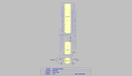
Schematic

The perfboard layout for the components is shown in this PDF:
View attachment temperature_monitor_perfboard.pdf
BOM
The BOM is just for the electronic components with a single BS18B20 sensor and does not include the perfboard, SPST momentary N.O. switch or connectors.
View attachment temperature_monitor_bom.csv
Source Code
https://github.com/barrongreig/TemperatureMonitor
Enhancements
A couple of useful enhancements to this project could be:
- Use microcontroller pin RA1 for throttle pulldown, battery charger disconnect etc.
- Use a slightly more expensive Pic with EEPROM, such as the PIC16F17114, along with software modification, and store a mapping between sensors and sequence numbers in the EEPROM.

