* * * THE BRUSHLESS BMC MOTOR * * *

It does seem that the measurements are not really consistent with the required relationships. But it's real data. Perhaps there was some other change made between the tests (length of wire?).

Where did you get your no-load current and resistance from?

The no-load current must be higher at 48v than 36v.
The resistance has to be constant.

I wonder if MAC-BMC has any published motor data?

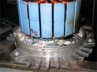
With some disassembly, I could measure the no-load current at a few voltages. Seems like I could also measure the resistance, but I don't have a good way to do that at home.
 
fechter said:
It does seem that the measurements are not really consistent with the required relationships. But it's real data. Perhaps there was some other change made between the tests (length of wire?).

Where did you get your no-load current and resistance from?

The no-load current must be higher at 48v than 36v.
The resistance has to be constant.

:arrow: None of it makes any sense...

The no-load is what it has to be in order to fit the rest of the relationships. (and is similiar to what brushed motor have) The resistance is the thing that bends the shape of the power curve. In order to get the proper bend you need numbers that are about par for copper wire like in a Unite motor... at least for 36 Volts. At 48 Volts the data comes in waaaaay too low to fit the resistance at 36 Volts and so in order to get anywhere near it you have to increase the resistance to an unrealistic value like 0.4 Ohms. A typical Unite motor has 0.2 Ohms (my 1000 Watt does) to something like a 0.25 Ohms like in a 1200 Watt Unite. The Brushless 5304 was using a value of something like 0.3 Ohms to the best of my recollection. The "mighty" PMG 132 uses 0.025 Ohms, but they use a different technology so you can't expect to touch that number with regular copper wire. (you spend $1000 to join a different higher performance club)

It looks like the 48 Volt data was either purposely "fudged" so as to pass below the radar of the law (allowing people to ride a motor that has an actual 2 hp rather than the posted 1.5 hp) OR the controller has some sort of serious dysfunction that takes place at 48 Volts where it simply works really bad. Have you noticed how the efficiency for the rated value of the 48 Volt is LOWER than the 36 Volt? That's another red flag that something is really wrong.

I really don't know what is going on here... something is not right with the dyno data in my opinion... :shock:
 
knowing the actual no-load current and resistance would be a good starting point to figure out how to fit the rest of the data.

At 48v, the motor is spinning faster, so the core and windage losses will be greater. This will cause the efficiency at 48v to be lower than at 36v.
That make sense to me.
 
fechter said:
knowing the actual no-load current and resistance would be a good starting point to figure out how to fit the rest of the data.

At 48v, the motor is spinning faster, so the core and windage losses will be greater. This will cause the efficiency at 48v to be lower than at 36v.
That make sense to me.

The no load was said to be 3 amps and with 125 rpms per volt. But those numbers produce something that is impossible. The curves do not line up at all with those dyno numbers.

I can see the windage losses increasing moderately as the rpms rise, but not to answer for what these numbers suggest. Something is seriously screwed up with those dyno numbers at 48 volts, but at 36 volts the motor looks to be about the same as a comparable Unite motor, with just some slight efficiency advantages. So it might be easiest to just assume that the 36 volt numbers are the "real" ones and that the 48 volt are somehow suspicious. The more you can actually test your motor and report your findings the better because the information seems to not exist anywhere on the internet.
 
I can ask Tim how the measurements were made. It does seem like something is a bit out of whack.

Try ignoring the 48v numbers and just use the 36v set for now.

I''ll see about rewiring my scooter and pulling the belt off to get a *real* no-load current measurement.
 
Perhaps I can shed some light on this subject:

I asked Tim this :

> > I'm confused. I read your webpage, and I can't find any info on a 1000W
> watt motor I saw on this webpage:
> >
> > http://www.thesuperkids.com/600wahspsuto.html
> >
> > They claim your motor is 1000W, but your webpage asys its more like
750W.

And he answered:

> The 1000 watt motor at Superkids is the same as my 750 watt motor-
they
> just choose to advertise it as 1000 watts. Technically they aren't exactly
> wrong, since the system can in fact put out a good deal more than 1000
> watts- just not continuously. I always stick to continuous ratings, since
> anything else can be confusing.

Draw your own conclusions.
 
OK, I rewired things so I could measure the no-load current on my BMC motor. Here are the results:

3.2A @ 49v
2.6A @ 37v
2.2A @ 25v

Fluke accuracy, but there was a bit of bouncing around, so the numbers are rounded.

To fully characterize a motor, we should only need to know the no-load current, the winding resistance, the voltage constant, and the torque constant. With these 4 items, it should be possible to simulate the motor fairly accurately.
 
fechter said:
Here are the results:

3.2A @ 49v
2.6A @ 37v
2.2A @ 25v

Well, if you use the standard brushed motor formulas (spreadsheet) and plug in the value of the no load current at those different voltages you would get for the motor resistance:

49v - 0.1515 ohms
37v - 0.1411 ohms
25v - 0.1126 ohms

So those "weird" kinds of results seem to match the stuff that is published for the BMC. My guess is that other formulas apply and the brushless is behaving differently. We're missing something.

Reverse Engineering

If you look at it the other way and ask:

"What should the no load current values be if this were a brushed motor?"

...and you would get: (if you start with 48 volts and work backwards)

49v - 0.1515 ohms - 3.2A
37v - 0.1515 ohms - 2.4A
25v - 0.1515 ohms - 1.6A

Now it's possible that measurement error could be going on, but since there seems to be a linear relationship other than what we expect based on the brushed formulas this seems to point to an "unknown" behavior.

:arrow: Brushless motors are not the same as brushed motors it seems...

How would you begin to apply formulas that apply to brushless motors?

The formulas for brushed motors all check out perfectly with motors like the PMG 132 and others that publish how they behave.
 
The no load current is a function of the winding resistance, the voltage applied, and the efficiency of the motor. Core and windage losses are in the no load measurement, not just resistance. Core and windage losses are not linear functions.

To find the winding resistance, we really need to measure it with an ohmmeter. Unfortunately, I don't have what it takes to make a reasonably accurate measurement at home. Perhaps I can improvise something from the junk pile.
 
Brushless motors are not the same as brushed motors it seems...

Well, no fooling. I will disagree with Fechter here - the equations are not the same. With DC, you can get by with algebra. With AC, better brush up on your trig and integral calculus.

If you're only dealing with synchronous motors, then deal with apparent, real and reactive power. Is is straight V/F, or closed loop?

As far as meters go, Fluke makes good ones. You might check the specs for the 125 - made for motor control applications, it measures most of these things diirectly. Interestingly, it also has a mode for measuring PWM waveform values direclty - because it isn't the straight DC stuff you model or measure. Both Fluke and Tektronix stuff is good - but it's only accurate if it's calibrated. Something you've had in your toolbox for 10 years (or even only 1) might be off a few percent.

When it gets to induction machines, things get much trickier. You need to model slip and vector control - maybe you need Mathmatica, rather than Mocrosoft Works.
 
I was measuring the current between the batteries and the controller, and it was at full throttle, so the PWM duty cycle was 100%. There is some loss in the controller, but at no load, the error from this is minimal. I suppose I should measure the controller idle current and subtract that (I did not).

I think under my test conditions, the numbers should be very close to those of a brushed motor.

Measuring the motor current on the motor wires is another story, as you are pointing out. I can't even imagine what happens on an induction motor where you have a large phase difference between voltage and current. I'm trying to keep it as simple as possible.
 
If you know three or four data points for a brushless motor at a given voltage you can fit a curve that does a decent job of approximating it's behavior (we hope) using the brushed motor equations. But it does seem that Patrick is right, the brushless motor is less bound by the formulas for the brushed motor.

It's a little like the discussion had here about Power and Torque. If you view everything through the eyes of Torque (like in a hub motor) things are very simple. But when you introduce gears you have to rethink everything because now you are focused on Power which is a derived value of both Torque and Rpm.

Windage losses (as in the air resistance inside the motor) seems like something that should not effect the motor that much.

I'm hoping you (Fechter) and Patrick will start a debate about all this so that the more novice folks like myself can begin to absorb the ideas. 8)

The brushless motor and a programmable controller seem to be adding "virtual gears" by using electronics alone...
 
Patrick said:
With DC, you can get by with algebra. With AC, better brush up on your trig and integral calculus.

That's fine with me. I have two college degrees in the sciences and took the physics series all the way through to the end. (2 years) Took the math series too. (1 year) I've only been studying/riding electric motors since last september, so you have to figure that it takes some time to absorb it all. I think you are right that the brushless motor introduces an extra level of complexity and a further separation from the hardwiring of the motor. With the a/c current you can shift the apparent behavior of the motor without changing the physical charactoristics of the motor.

My calculations show that gears can roughly double the effective performance range of a fixed powered motor. If you double the power output of a motor you get the same thing as if you take the original power and add gears. In the motorcycle world where power is "whatever you want it to be" you are free to increase the power output indefinitely. In the bizarre legal world of the electric bike there is this power cap of 750 watts to stay legal and unregistered. This is a very important thing to observe... you can't exceed the power limit. (at least at the point of sale) However, if it were possible to widen the powerband so that across a much wider range of rpms you could get the same legal power output then that might be of real value. (assuming the efficiency is good)

On the bicycle side the legal stuff trumps some of the technical stuff.


Ideal Powerband

For the legal electric bike the "ideal powerband" would be 750 watts from zero rpms all the way up to the maximum rpms and have high efficiency too.
 
Hi all
I've just read through this whole thread and think I can contribute although it has gone quiet for 3 weeks.
I have just got a blown scooter motor from tim with the D rotor fitted so I can convert it for use with my USPD setup, its a pig to do but I have converted the smaller motors over before.
I found out that although various people have said that the BMCs have advanced timing built in to the motor by means of hall sensor positioning I don't think this is the case I think the advance timing is built in to the internal speed controller, my opion for this is that after converting the smaller motors to external speed controller the performance/ max speed unaided was slower :!:
I am concentrating on my electric chopper convertion using a hub motor I have until the start of august to get it finished so most of my time is taken up with this. When finished I will start on the BMC motor, by that time a 72v 40a controller and a CycleAnalyst should be here from Ebikes.ca.
I will then start to find out info about the BMC and what it can can do.
Will give more info after the 10 august should have the BMC converted and ready for testing.
 
I think you're right about the timing.

The one I'm using needs to rotate in the reversed direction compared to stock. Once I got the halls sorted out, the no-load speed and current are the same in either direction, indicating there's not much difference in timing. The hall sensors are centered in the slots, so mechanically I don't see how it could be advanced.

If you're lucky, the wires won't be burried too deep in the epoxy like mine were.
 

Attachments

  • Hall Sensors.jpg
    Hall Sensors.jpg
    56.1 KB · Views: 2,134
  • BMC hall wires.jpg
    BMC hall wires.jpg
    57.3 KB · Views: 2,133
  • BMC phase wires.jpg
    BMC phase wires.jpg
    63.7 KB · Views: 2,134
Safe thanks for this thread. I purchased this motor just now from powerpack. My spreadsheets show a good price point at 36v with lithium ion cells, so I'll try running it at that voltage.
 
Back
Top