The (Cheap) Programmable Controller

safe

1 GW
Joined
Dec 22, 2006
Messages
5,681
The (Cheap) Programmable Controller

I'm going to post the charts first and then link to them. (it makes it easier to read)
 

Attachments

  • Duty Cycle - Programmable.gif
    Duty Cycle - Programmable.gif
    8.1 KB · Views: 3,645
  • Duty Cycle - Battery Current Limited.gif
    Duty Cycle - Battery Current Limited.gif
    8.1 KB · Views: 3,643
  • control knob analysis.gif
    control knob analysis.gif
    11.1 KB · Views: 3,593
  • lessor of the two.gif
    lessor of the two.gif
    6.1 KB · Views: 3,557
  • programmable over bcl.gif
    programmable over bcl.gif
    10.2 KB · Views: 3,510
  • control knob analysis 002.gif
    control knob analysis 002.gif
    10.9 KB · Views: 3,471
  • default chart.gif
    default chart.gif
    2.6 KB · Views: 3,467
  • MY1016Z3 Programmable.gif
    MY1016Z3 Programmable.gif
    8.2 KB · Views: 3,420
Duty Cycle

The Duty Cycle is just a fancy term that describes the percentage of time that the PWM controller is "on" verses it being "off". The higher the duty cycle the more you are opening the throttle.

The Current Limit of a standard controller is designed around what the battery is showing as it's current drain. So when you have something like a 30 amp current limit controller that means that the Duty Cycle will be forcefully reduced (whether you like it or not) to a level that drops the battery drain rate to a level that matches the current limit.

:arrow: This standard controller system is basically called "Battery Current Limiting" and looks like this:


duty_cycle__battery_current_limited_120.gif
 
Armature Current Limiting

Instead of basing your current limit on the battery side of the system it's also possible to measure the current that is going into the armature of the motor. This is called "Armature Current Limiting". I've used the term "Motor Current Limiting" in the past, but I'm doing what I can to upgrade to what seems to be the more accepted naming convention. It might seem odd that there is a difference between the armature current and the battery current, but I'm not going to go into that here. It took me months to realize that such things were going on.

The "Armature Current Limiting" system will give performance that looks like this:


duty_cycle__armature_current_limited_120.gif
 
Programmable and Cheap

This is the core of where this thread needs to go...

I want to explore what it might take to create a programmable controller modification circuit that would have a few components:

:arrow: Rpm motor sensor - Some kind of sensor that would give as it's output a voltage from zero at zero rpm to a larger voltage as the rpm increased. Since this will be an analog circuit it doesn't matter all that much what the voltage is. (for our purposes)

:arrow: A "Starting Duty Cycle" setting. One of the trim knobs would establish the baseline voltage for the allowable Duty Cycle. This is the low end adjustment part.

:arrow: A "Ramp Rate Duty Cycle" setting. This is the second trim setting that would determine the slope of the line of the Duty Cycle and create the ramp rate towards full throttle.

Between these few elements I think you could with just a few elements design a circuit that could offer much in the way of having a programmable controller. If you turn the starting setting knob up to full open you would get the default Battery Current Limited controller "personality". If you set the knobs just right in the middle somewhere you would get a behavior like the Armature Current Limited "personality". And lastly you could create a really peaky powerband if you dropped the starting position knob really low and set the ramp rate to be rather high, then you get the Programmable Current Limit "personality" seen here:


duty_cycle__programmable_120.gif


...what's really nice about this is that you also can configure things so that you are effectively getting a lowered current limit when you want it. Between these two knobs you can just about deliver all the combinations that a controller CAN deliver. 8)

This circuit could be built as an add on...
 
Why?

What prompted me to think of this is that when you look at the way something like "Ice Cooling" the outside of your motor shell works it's ability to cool is closely tied to motor rpm. The faster the motor spins the faster the heat from the rotor is transferred to the shell and then off to the ice for cooling. I also realized that with gears you can keep this kind of motor in the powerband pretty easily. (I've ridden plenty of peaky powerband motorcycles before) The only weak spot is 0-5 mph in first gear, and I'm thinking I would in those cases actually use the pedals. (it gives purpose to pedaling) So basically if you want to short shift the bike coming out of a turn you could get up and give a few hard pedals to get going and then the powerband "hits" and you can sit down and let the motor take over to do the rest. :)
 
How The Adjustments Would Work

There are two control knobs, one that adjusts the baseline "starting" Duty Cycle and the other that sets the rate at which the Duty Cycle is permitted to rise with motor rpm. Setting the starting Duty Cycle to it's maximum would make the "personality" revert back to the Battery Current Limited behavior. (or unlimited if you were using a controller without a current limit)


control_knob_analysis_172.gif
 
Hall Effect Speed Sensor

From what I can tell the typical Hall Effect Speed Sensor produces a square wave as output. Ideally for the circuit I had in mind the output would be a fixed current, but I suppose there have to be ways to flatten this output.

image.ds.drawing.hs.jpg


...once you got the output flattened you would have some kind of logic that went like:

:arrow: If the baseline throttle voltage (0-5V) is higher or lower than what this circuit arrives at then you need to always take the lower value out of both.

:arrow: Take the (scaled) sensor output (knob #1) and add it to the starting voltage (knob #2)... if the result is below what the throttle voltage is then take the lessor value.

Something like this anyway... :roll: (needs to be thought out more)

lessor_of_the_two_148.gif
 
Programmable Circuit On Top of Regular Controller

This is what you get when you adjust the programmable circuit so that it has an impact on the low end, but let's the top end run at full current. You could use this circuit in so many ways that it's kind of funny that it's not thought of more. (it's like having total control over your motor)

This is really cool folks! 8)


programmable_over_bcl_188.gif
 
???

I'm not sure how you could build a circuit to do all that without resorting to a microcontroller. I'm not so good at writing code.

I'm sure there is an analog way also, but it would involve a lot of tweaking. Let my brain digest it for a while...
 
fechter said:
Let my brain digest it for a while...

I just wanted to get the mind spinning. :lol:

After you get the sensor current leveled out it's not that complicated.

You might try to think of a circuit WITHOUT the startup voltage knob first.

So the only thing you would be doing is taking the (smoothed and scaled by the control knob) sensor current and comparing it to the throttle voltage.

Whichever is less.

(pretty much the same as the armature/motor current limiting circuit)

So looking at the chart you can just remove the green color.


lessor_of_the_two_148.gif


As I recall, voltages in series have an additive effect, so when you do finally add the startup voltage (scaled as well by a knob) it just adds to the speed sensor component.

You then use the comparator to compare two against one.


Smoothing

Seems to me that since "whatever" you get from the speed sensor gets scaled by the control knob, there's no reason you couldn't just average out the square voltage. Maybe some sort of capacitor or something.

It might also be possible to think of a different type of sensor that produces a smooth current... maybe something more like a generator?
 
Analysis of the Control Knobs

Hopefully this gives a better overview of how these control knobs in the circuit would effect the motors powerband. The colors are the same as the previous charts, so red is heat, power is black and blue is the duty cycle.

control_knob_analysis_002_291.gif


The standard "personality" (unrestricted by the circuit) would look like this.

:shock: Look at that red line... it's no wonder that when people try to overvolt their motors they tend to run into trouble.


default_chart_154.gif
 
Though not cheap, the controller in the Goped ESR is programmable. Two performance modes (Turbo and Econo) are available with a handlebar mounted switch. Both modes can have the top speed and acceleration parameters set individually. Unfortunately the programming interface must be purchased seperately and it isnt inexpensive at over $200. Its intended as a Goped dealer tool but I purchased my own for fun.
 
Low Pass Filter

180px-Capdivider.svg.png


One simple electrical circuit that will serve as a low-pass filter consists of a resistor in series with a load, and a capacitor in parallel with the load. The capacitor exhibits reactance, and blocks low-frequency signals, causing them to go through the load instead. At higher frequencies the reactance drops, and the capacitor effectively functions as a short circuit. The combination of resistance and capacitance gives you the time constant of the filter τ = RC (represented by the Greek letter tau).

http://en.wikipedia.org/wiki/Low-pass_filter
 
v_tach said:
Unfortunately the programming interface must be purchased seperately and it isnt inexpensive at over $200.

I'm hoping to build either a straight forward armature current limiting circuit (for next to nothing) or a more sophisticated dual knob programmable circuit. (also for next to nothing)

The dual knob would give me precise control that would equal (or come very close) to the abilities of an expensive controller.

If the circuit can be made for $25 each (or so) then I'd make one for all three bikes I'm building or own... :)
 
I'm all for cheap and next to nothing if the functionality and reliability are still there.
 
v_tach said:
I'm all for cheap and next to nothing if the functionality and reliability are still there.

Keep in mind that we're not actually talking about building a controller from scratch, but to build a circuit that puts some extra current limiting on top of the default current limiting. One would figure that in the worst case scenario things would just revert back to the default controller personality.

:arrow: With this type of circuit you can always just turn it off if something isn't working correctly.

The default controller personality:


default_chart_154.gif


control_knob_analysis_002_291.gif
 
MY1016Z3 Programmable

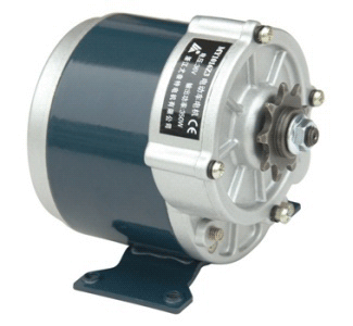
If you take the stock 350 watt rated MY1016Z3 that normally uses 24 volts and increase the voltage to 36 volts and connect it with a 40 amp controller you will likely burn up your motor because of excessive heat. But if you take this same upgrade and add "Ice Kissing" (ice wrapped around the motor shell) and add this programmable controller circuit so that you can REDUCE the heat then you should get a bike that will handle the heat and be able to reach somewhere in the 45+ mph range using multiple gears. (given some good aerodynamics)

:arrow: The effects of the changes caused by this programmable controller concept looks something like this for the MY1016Z3 (all the values are watts):


106115.gif


my1016z3_programmable_117.gif


This motor weighs 2.799 kilogram = 6.170 lbs
 
Fechter... I hope you're still thinking about this idea.

:arrow: Do you have any questions about what I have in mind?

As I see it you need to smooth the sensor square wave with a capacitor and a resistor, run it through a pot to scale it, then combine the result with what you get from a pot that establishes the starting voltage. You take these two series voltages (combined) and use a comparator to compare it to the throttle voltage.

I think that's all it will take... :?


image.ds.drawing.hs.jpg

180px-Capdivider.svg.png
lessor_of_the_two_148.gif
 
The filter will work to give a voltage porportional to motor speed.

Somehow I'm still not clear on the overall concept though.

Why would you want to start with an output other than zero?

It would also be really helpful if your graphs had both axes labeled and the lines labeled. I don't like to guess.
 
fechter said:
The filter will work to give a voltage porportional to motor speed.

Somehow I'm still not clear on the overall concept though.

Why would you want to start with an output other than zero?

It would also be really helpful if your graphs had both axes labeled and the lines labeled. I don't like to guess.

default_chart_154.gif


Let's start with what the lines mean. The red line is heat, so it's based on the current value times the resistance. The black line is power. The blue line is the duty cycle. If you look carefully you see that with this default controller chart the duty cycle starts WELL ABOVE zero when the throttle is opened. The controller is limiting the current by reducing the duty cycle... hopefully you are going "oh yeah" right now. So in a typical controller you might actually start with a duty cycle of about 40% if you crack the throttle wide open from a standstill. Again you are nodding your head and saying "yep".

:arrow: As you reduce the starting duty cycle towards zero you are choking off the low end torque.

The other knob adjusts the rate at which the duty cycle is allowed to increase RELATIVE to the starting duty cycle and the motor rpm. Basically you have two knobs... one adjusts the low end starting point and the other adjusts how fast the power comes on. (the ramp rate) At some point if you turn these two knobs open all the way the duty cycle is relaxed to such a degree that you intersect with the default controller personality.

:idea: Think in terms of heat... look at the red curves in all these charts and then compare it to the stock chart. All these motors are going to run cold and with gearing they will still be very usable because just like a road racer motorcycle you shift from peak to peak.

I want a motor that produces great peak power, but doesn't create low end heat... basically I'm creating a race bike powerband.


control_knob_analysis_002_291.gif


The final Throttle Voltage equals the Duty Cycle.

lessor_of_the_two_148.gif
 
safe said:
The blue line is the duty cycle. If you look carefully you see that with this default controller chart the duty cycle starts WELL ABOVE zero when the throttle is opened. The controller is limiting the current by reducing the duty cycle... hopefully you are going "oh yeah" right now. So in a typical controller you might actually start with a duty cycle of about 40% if you crack the throttle wide open from a standstill. Again you are nodding your head and saying "yep".

Err... Nope.

If you start out at 40% duty cycle, the cycle will try to jump out from under you. It would almost be like having a relay and a battery feeding the motor. When it turns on, bam! you'd have a sudden jerk.

The duty cycle needs to start out at zero.

If you start out at 40%, I think the limiter would kick in immediately to drop it closer to zero.

You want the duty cycle to be able to hover near zero when you want to creep slowly.
 
fechter said:
The duty cycle needs to start out at zero.

Boundry conditions can sometimes create confusion. Rather than discussing "zero" let's talk about what approaches zero. So let's talk about "very low rpm". At very low rpm the efficiency drops towards zero. So the duty cycle is higher than what you might expect based on the power output. A 40% duty cycle at very low rpm translates to very little power output... just enough to get the bike moving.

Compare a duty cycle at 100 rpm to the duty cycle at 3,000 rpm. At 100 rpm you have nearly all your energy going to waste in the form of heat. At 3,000 rpm the duty cycle produces power output in closer relation to the power you put into it.

But I think you're not quite getting the concept yet... :?

All the charts are based on the idea of full throttle 100% of the time. As Xyster has pointed out before there is an infinite variety of "throttle fiddling" that you might do and you could in theory create any "personality" for a motor that you could ever want with meticulous throttle restraint.

:arrow: But that's what this circuit is suppose to do.

The idea of any current limiting scheme is to restrict what would otherwise be an open flow of power. So the programmable circuit is simply INCREASING the restrictiveness compared to the stock controller and yet the underlying electronics of the controller are not affected.

If you reduced the starting (zero motor rpm) duty cycle truly to zero, then when you opened the throttle to wide open the bike wouldn't move. :lol: If you pedaled up to speed a little and the motor sensor started to allow the circuit to open up more then the final throttle setting would ease it's way open. This would end up being a kind of "pedal first" controller scheme.

Ideally you want to get the starting duty cycle (knob) set to about 10% and ramp up the duty cycle with rpm at a rate so that it intersects the stock controller at near it's peak power point. By setting it a little before the peak you get a wider powerband.

This "ideal" motor personality would look like this: (notice this is a comparison of stock motor verses altered... see chart below)

I hope this is beginning to become clear "through the fog" because it's going to be a really cool circuit. At this point I could probably do it myself, but I'd prefer you to understand it and create a diagram.


If it helps any, I'm 100% certain of what I'm doing here... so when in doubt you need to assume you aren't understanding what I'm presenting. It's just a slight variation of the Armature Current Limiting idea, but this time there are two control knobs rather than just one.


my1016z3_programmable_117.gif
 
Review of the Basics

:arrow: The Duty Cycle in these charts are scaled so that 1000 equals 100%.

:arrow: The Power is in Watts.

Take a careful look at the way the Duty Cycle behaves. These are three stock controllers, 20 Amp, 30 Amp and 40 Amp at 48 Volts. Basically the "ramp rate" is about the same for the different controllers, but the starting Duty Cycle is higher for a higher controller limit. For this default type of limitation system the Duty Cycle lines aren't perfectly straight, but actually have very subtle bends to them. However, for our programmable circuit we can use true straight lines and get good control.

I know it's "inside out" to think this way, but this is what is really going on as far as the Duty Cycle.
 

Attachments

  • 1200 Watt 48V - 20 amps.gif
    1200 Watt 48V - 20 amps.gif
    4.8 KB · Views: 3,154
  • 1200 Watt 48V - 30 amps.gif
    1200 Watt 48V - 30 amps.gif
    5 KB · Views: 3,155
OK, I understand the duty cycle part if the condition is accelerating from stop at full throttle.

So, you want to make the current limit a function of motor rpm?
 
Back
Top