the cruzbike electric

Thanks, I see now. It's hard to see in the pics, but the rollers are offset slightly. This works similar to the roller clutch on a Currie drive.

After some miles, it may be necessary to clean and re-grease the rollers.

Heat buildup could be a problem. Forced-air cooling would be a bit tricky to set up on a hub motor.
 
the motors are rated 200-300w but mine seems to run fine at twice that. i have been told the plastic gear is available as a replacement part and that seems like the most likely part to fail. if i ever get around to taking it apart i will definitely add a thermal sensor to the motor.

i apologize for not knowing more about the motor; i tried it for a few weeks and decided to go for more power. i am keeping it around in case i need to use the bike somewhere that has more restrictive power limits. the motor is so small and quiet that i believe nobody would expect it to be over a 200-300w limit, and the adjustable controller makes that a reality if it is set low enough.

there is lots of data including mechanical drawings on nuergy.com
 
Very intriguing planetary system! Are the rollers solid metal, or are they composite with nylon?

I tried to find more info on that type of drive, but no luck yet.

Bob: have you got a link or another address?

:?:
 
nemo said:
From what I saw inside:
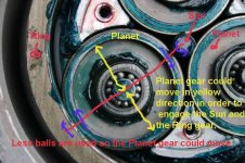
I think that the force is maintained on rollers by clever mechanical design when the motor spindle(shaft?) in the middle is one firm point, 3 wheels can shift a little bit and engage themselves against barrel on the outside , again a firm point.
It's done by using needle bearing inside the 3 wheels with not enough needles.(img7973) so the wheels doesn't stay centeredhere.

Agreed.
You have an excellent observation.
The motor spindle acts as the SUN gear.
The 3 wheels act as the 3 PLANET gears.
The barrel acts as the RING gear.
All these gears are teethless.
Friction is required for transmitting motion.

In my opinion, the shifting action of the PLANET gears could also act as an free-wheeling.
 

Attachments

  • img_7973_617 copy.jpg
    img_7973_617 copy.jpg
    87.8 KB · Views: 5,948
fechter said:
Thanks, I see now. It's hard to see in the pics, but the rollers are offset slightly. This works similar to the roller clutch on a Currie drive.
.

An site says about the free-wheel on an teethed planetary geared P3 motor:
"This motor uses a freewheel mechanism as shown below. Its a very robust design. The motor drives the planetary gears which in turn drive the circular metal plate shown with a red arrow indicating motor spinning direction. The small rollers wedge themselves onto the hardened metal plate but when the motor is not spinning the plate can rotate freely hence the wheel can rotate freely. There is negligible resistance when freewheeling the same as a normal biycycle wheel"
 
TylerDurden said:
Very intriguing planetary system! Are the rollers solid metal, or are they composite with nylon?

I tried to find more info on that type of drive, but no luck yet.

Bob: have you got a link or another address?

:?:

sorry, the website is http://www.ethinkar.com

ethinkar / nuergy / tarn are all names used for these motors
 
bobmcree said:
TylerDurden said:
Very intriguing planetary system! Are the rollers solid metal, or are they composite with nylon?

quote]

I'm 99% sure they are all metal. I tried to scratch the weels with the screwdriver. :)
 
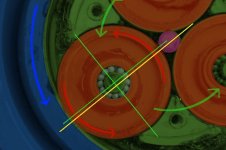
The only way I can understand this to work is for the carrier to be the driven element:

Carrier -> Green
Case -> Blue
Planets -> Red
Axle -> Purple

The space between the axle and the case is too small for the planet, so the planet must roll against both when pushed into the gap by the carrier.

Arrows indicate motion relative to axle.
Axle = 0 rpm
Carrier = 12 rpm
Planet = 4 rpm
Case = 1 rpm
(approx)

:?:
 

Attachments

  • img_7973_617b.jpg
    img_7973_617b.jpg
    55.8 KB · Views: 5,618
TylerDurden said:
Carrier -> Green = Planet CARRIER
Case -> Blue = RING gear
Planets -> Red = PLANET gears
Axle -> Purple = SUN gear

For panetary gear:
Any one of the four could be the INPUT.
Any other could be the OUTPUT.
See:
http://auto.howstuffworks.com/gear-ratio4.htm

Your ratio and direction are correct if the CARRIER is used as input and the RING is the output.
 
For nemo's TARN motor:
The SUN is the input.
The CARRIER is stationary.
The RING is the output.

Talked with a good friend of mine who is in mechanical engineeing/profession yesterday.
He commented that the teethless planetary gear has shorter life and lower efficiency than the teethed one.
 
The7 said:
For nemo's TARN motor:
The SUN is the input.
The CARRIER is stationary.
The RING is the output.

Talked with a good friend of mine who is in mechanical engineeing/profession yesterday.
He commented that the teethless planetary gear has shorter life and lower efficiency than the teethed one.

I suspected that the teethless planetary gear has shorter life and lower efficiency..and now you got it conformed from your friend.

I'll see what happens with mine TARN in a couple of months. I ride my folder nearly every day for about 5miles.
What I love about it is the noise or rather silence....

I also found that MC33035 3 phase IC driver, common in many controllers, has max voltage of 40V. That's max rating. Not recomended which is 10-30V.
So I just might get away with dewalt battery (36V absolute max)
Not good with 36V nicd or nimh !
Also there might be some controllers with different design that uses MC33035 and will be ok with higher voltage.
Not mine I think. Interesting is that the mosfets on mine are up to 80V(datasheet)
:D
 
The7 said:
]
I also found that MC33035 3 phase IC driver, common in many controllers, has max voltage of 40V. That's max rating. Not recomended which is 10-30V.

:D

i don't know where you got the 40v spec but it is incorrect. the absolute max rating according to the datasheets i have for the original motorola part used in the kollmorgen controllers i have been using for years is 30v and i know for a fact that several people have blown them at 36v.

do you have a data sheet showing a 40v rating?
 
bobmcree said:
The7 said:
]
I also found that MC33035 3 phase IC driver, common in many controllers, has max voltage of 40V. That's max rating. Not recomended which is 10-30V.

:D

i don't know where you got the 40v spec but it is incorrect. the absolute max rating according to the datasheets i have for the original motorola part used in the kollmorgen controllers i have been using for years is 30v and i know for a fact that several people have blown them at 36v.

do you have a data sheet showing a 40v rating?
here:
on page 3
http://www.onsemi.com/pub/Collateral/MC33035-D.PDF

Vc30,Vcc40V...can you explain? Thank you
 
nemo said:
bobmcree said:
The7 said:
]
I also found that MC33035 3 phase IC driver, common in many controllers, has max voltage of 40V. That's max rating. Not recomended which is 10-30V.

:D

i don't know where you got the 40v spec but it is incorrect. the absolute max rating according to the datasheets i have for the original motorola part used in the kollmorgen controllers i have been using for years is 30v and i know for a fact that several people have blown them at 36v.

do you have a data sheet showing a 40v rating?
here:
on page 3
http://www.onsemi.com/pub/Collateral/MC33035-D.PDF

Vc30,Vcc40V...can you explain? Thank you

thanks for the data sheet. it appears that the ON Semiconductor parts will tolerate a higher Vcc (supply voltage) than the original motorola parts. this is good to know, but i would not take it to mean that existing controllers using the older parts can handle the higher voltage. The Vc spec is the maximum voltage the chip can output to drive the low side fets in an h bridge.

i did not mean to come on so strongly about the 30v spec or sound like i was doubting your word, but i have been reversing and selling the kollmorgens for quite awhile and i don't want people to think they can run them at the higher voltage and then complain to me when they blow. the a123s run at 33v after a slight discharge, and their internal impedance is high enough that at the 30A + that these motors draw they will be well below 30v, so they might hold up, but i do not warrantee the motors i sell above 24v.

the kollmorgen motors using the motorola mc33035p have repeatedly blown when people run them at 36v. they are of course a 10 year old fab, so it's good to see ON has improved the parts, probably by refining the fabrication process. too bad most controllers using these parts are potted, so it would be difficult to swap in the new parts.
 
Just wanted to say "Thank god this wasn't consumed and deleted by the forum monster"!

This is very neat. I like the ergonomics and aerodynamics of a recumbent (I hate mountain bike positioning for pedaling, which is probably why I added an electric motor so I wouldn't have to pedal.), but the lower visibility "height" along with the non-standard wheel spacing (So things like bike-racks can be used) has been off-putting. So the cruz-bike looks like a very interesting possibility.

I wonder, would it be possible to route the chain to the back wheel just so you don't have to undergo an "upper body" work out? Or are the pedals and crank like directly linked to the steering column stem with the cruz-bike? It would be better if power could be applied to the back and not get the wobbly-front syndrome from pedaling up there. But, a FWD looks like it'd free up some precious room for an RC drive in the back.

Also, has anyone noticed handling/stability problems at speed? It seems many claim problems with short-wheelbase bikes with handling at higher speed, but maybe a recumbent doesn't need to be long to be stable at higher speed? Maybe FS mountain bikes are good enough. I'm thinking of speeds like 35 mph.
 
There are recumbents with dual big wheels that are rear wheel driven. Lots of them.
Here are the two most common I can find in shops around.
http://www.bacchettabikes.com/
http://www.ransbikes.com/

Cruzbikes with the moving bottom braket and front wheel drive are rare for recumbents which are in turn rare for a type of bicycle. The cruzbike does pivot the whole front end from the former seat post of the MTB doner so routing it back wouldn't work for it. I put about 6k miles on a Bacchetta Giro 26 (dual 26" wheel high racer) before switching out to my Challenge Hurricane (dual 20" quasi low racer) and speed isn't a problem for either bike and both are rear wheel drive. I also have a sofrider as pictured early on in this thread that I'm cutting down and rebuilding the frame so the seat is about 12 inches lower. The "upper body" workout isn't really a big deal you can pedal with just one hand barely on the steering after a certain time but if you _want_ to you can throw your upper body into the mix unlike most recumbents where you lay back reclined and mostly spin your legs.
Note: The Giro 26, Hurricane and Sofrider all fit on bike racks I’ve tried.


The cruzbike is different because of how it sort of pivots in the middle right under your butt but from what I hear it doesn't give a problem and so far I haven't found it to have an issues rolling down hills or slight declines in the 30s but I'm still under 1000 miles with it and I personally don't like the seat height so I'm fixing it by rebuilding the frame.
Now the Giro 26 and Hurricane I have lots of riding experience for commuting and long 200+ mile rides and have had both over 50mph down hill for miles at a time with some slight corners thrown in and I had no fear of anything going wrong. I felt a little safer on the hurricane with curve hugging rear suspension and more solid seat though it fits like an extension of my body. I regularly took them both on some multi mile sprints of 30mph to try and race traffic where it was flat or a slight decline or maybe a little tailwind and I never had an issue sometimes I hit 35 on my own power but I'd need both a tailwind and a long stretch of nice pavement on a slight decline to do that for any length.

It is interesting to see this post pop up.. Starting tonight I plan to start the welding of the new mid frame on my cruzbike as the first test donor for an electric motor. The dual suspension would be nice for keeping things on the ground and big wheels nice for absorbing road abnormalities but I don't plan on holding 35mph on it unless I'm pedaling that fast with a little assist. I've only read about jacknifing one a coupel times but if you are pedaling and the front wheel locks up during a shift the front of the bike will turn suddenly and dump you. Now if you throw in a rear motor into the mix that will help push you over more I don't think I'd personally want to risk that at 35 but I'm not terribly trusting of it yet. If I had a spare hurricane around I'd convert it but I don't and I don't want to risk harming my hurricane in any way since it is kinda irreplaceable as the new ones a quite a bit different now.
 
Any one remember this thread?

I have one of these, and it is very noisy, like the rotor is rubbing on the stator, so I guess that maybe the magnet ring is cracked link in the picture earlier in the thread.

Anyone know how the planetary case is stripped off? as it loks like that need to come off first in order to remove the rotor to check it.


Maybe it is not even repairable
 
NeilP said:
Any one remember this thread?

I have one of these, and it is very noisy, like the rotor is rubbing on the stator, so I guess that maybe the magnet ring is cracked link in the picture earlier in the thread.

Anyone know how the planetary case is stripped off? as it loks like that need to come off first in order to remove the rotor to check it.


Maybe it is not even repairable
Hey Neil
Amberwolf has one that he is using for a mid-drive and Amigafan has ordered some from Keyde. I think Jeremy is also using one on his folder and I am about to get a couple to try out on my wifes trike. They seem to only sell front ones.
otherDoc
 
Well mine is a rear sitting in 165 mm dropputs
Maybe someone will want the parts to convert to rear ?
 
Hang on to it as rears are rare. I would like to try a rear but with fronts so readily availible I think I'll try a front on my wife's trike first. She is not thrilled with that 16 lb 9c on the front wheel and wants better steering and more manuverability. It is quiet however. The quiet is what is attracting me to these roller motors and the light weight.
otherDoc
 
Well this one is extremely noisy
The outer ring' gear' is not cracked and without disassembly, cant see what is causing it, An internal bearing collapse, or very dry and rusted open bearing, or a magnet ring broken up (though it looks ok from the side) are possibilities

Can't see how the ring gear comes off. Any ideas?
 
http://www.youtube.com/watch?v=soALLHssvLY&feature=youtube_gdata_player

[youtube]soALLHssvLY[/youtube]
 
Resurrecting the dead again..this thread..and the motor.

Well i stripped my motor, and rebuilt it.

When in the wheel and fitted to the bike, it does not roll easily in the backwards direction..if you push the bike backwards it does not roll smoothly. I am guessing this is not normal..but can any one confirm this..that it should or should not roll backwards easily. It is sort of 'coggy' at the moment
 
Back
Top