The FIRST home-built downtube frame-mounted 48v battery pack

dnmun said:
also, since you will not be using the thermal breaker on your BMS, you can cut it out and install a small switch there to turn the battery on and off. then you don't need to use a separate switch for precharge and you don't have to leave the battery active when you leave the bike so it cannot be stolen if you hide the switch.
Just thinking- You can add a switch in series with the thermal breaker so you'd have the on/off switch and still have the safety device operational- the best of both worlds
 
Hey guys...

That is a fabulous idea about the switch!! The case itself as a switch already, one of those 5 pin systems with LED on the button.

Here's my question. How does this temp sensor switching work? When it gets hot, resistance is high, and then the two wires sort of becomes "open" ? Then that shuts off the BMS?

And then when the temp is normal, the wires are shorted, that's how the BMS stays open?

So the switch can be wired so that you short the wires to turn it on, and then you open the circuit to turn off the BMS/battery?
 
the thermal breaker is a bimetallic strip that pops open at the specified temperature. it is of no use to you here. you can mount the switch wherever you wish and run the two wire to it. tiny wire is fine since there is almost no current.
 
dnmun said:
the thermal breaker is a bimetallic strip that pops open at the specified temperature. it is of no use to you here. you can mount the switch wherever you wish and run the two wire to it. tiny wire is fine since there is almost no current.

So, I would cut it off and just wire it like a switch.

Now how does it actually work on the BMS though? Is it like some kind of low current switching and it will completely disable the MOSFET and disable power from flowing out of the ground cables on the BMS?

So then this would prevent my andersonPP (negative) from getting that spark each time I connect the plugs together?
 
the circuit current that drives the charging and output mosfets flows through those two traces running across the end of the board to the thermal switch.

i use it to turn the battery on and off on the ping BMS and on others too. much cheaper and easier to use than the complicated precharge circuitry with the mosfets and capacitors...
 
nukezero said:
I really wanted to get the VTC5's. But they were too expensive. But yeah, the 25R has simliar performance for like 30% cheaper. Anyhow, I'm fairly happy. These are one of the best high powered cells you can get from Samsung that's atleast 2500mAH. I'll upgrade again when Samsung comes out with a 3000mAH 30R.

the samsung 25R only has similar perfomrance at 5A :wink:
if you draw such low amps, many other cells will provide more Wh usable so there is not need to use a high C-rate cell at only 5A.
There is another discharge graph (i think it is 10A continuos and 30A peak) where you will see the real advantage of the Sony VTC5. Yes this cell is more expensive than the others, but it is currently the best of all 18650 cells at high amps.
 
as you can see from the graph, they have equal voltage sag. So i doubt there will be more difference at 20A discharge. Your statement is true of course for other cells like the LG-D1 though... that is why i added that one to the chart as well, to have some comparison. The LG D1 is better if you only draw 5A max or a bit more. At 10A+ i would stick to Sony VCT or 25R

Cool idea with the temp probe. I have an automatic anti spark that work fine as is...I have it at the bike. Having it at the battery is something very usefull
 
dnmun said:
the circuit current that drives the charging and output mosfets flows through those two traces running across the end of the board to the thermal switch.

i use it to turn the battery on and off on the ping BMS and on others too. much cheaper and easier to use than the complicated precharge circuitry with the mosfets and capacitors...

any idea how much volts comes out of this system? I have a LED light on the button that is I think 12V LED. Looks like the picture below.
 
dnmun said:
the thermal breaker is a bimetallic strip that pops open at the specified temperature. it is of no use to you here. you can mount the switch wherever you wish and run the two wire to it. tiny wire is fine since there is almost no current.

but wait a minute, if you turn it into a switch and then you turn it off let's say, then the BMS is shutdown, they you won't get the balancing. And you wont even be able to charge it since the battery negative terminal is cut off?

therefore, you have to switch it on first to charge and let it balance and leave the push button toggled on?

Then otherwise, before you connect the battery, you push off, then connect battery, then push on?

How would that work?
 
nukezero said:
alsmith said:
It seems to have separate terminals for the led so may be 3V. The only way is to try- other than asking the supplier?

it's 12V I found out.
Some have the resistor built in to drop the voltage from 12V, some don't so operate at the leds voltage of around 3V.
 
sorry doublepost
 
crossbreak said:
as you can see from the graph, they have equal voltage sag. So i doubt there will be more difference at 20A discharge.

thats wrong. its cheer coincidence they have similar graphs at 5A. At higher amps things will look different because its not the same chemistry :wink:
as i said, for only 5A you better take cells with more capactiy like the LG D1, Panasonic PF etc..

the graph at 20A (the green line is the outstanding VTC5): http://dampfakkus.de/highamps/523-vs%20lg+samsung.jpg
 
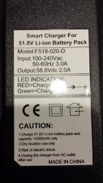
guys, I got my second charger today but the damn seller sent me another wrong charger. the good news is that this charger holds steady voltage. The bad news is that it is for a 14s, not my 13s pack. It is a 51.8V charger , output is 58.8Vdc.

The seller told me it will work fine with 13s, but I do not believe him. He says when it gets to full charge, it will turn into trickle charge mode... that may be true, but I'm still un-sure if I should still use this charger. He originally advertised it as 48v 54.6v output...

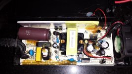
Anyhow, there is nothing in there that I can see that would allow me to adjust the voltage. No pot or anything. I plugged in this charger to my battery pack just now, and it works fine. For 3-5 minutes, I gained about 0.3V on the entire pack.

However, my question is, if my BMS is rated for 13s 48v, would it shut down the charger as well? of course, I'm not willing to try that to charge it up to find out. Please let me know. I still do like this charger because it's quite small, 2amps, and has a built-in fan. Just that the charger output voltage is 1 cell too high for my liking.
 

Attachments

  • ch.jpg
    ch.jpg
    70.5 KB · Views: 1,312
  • 20140521_182643.jpg
    20140521_182643.jpg
    96.9 KB · Views: 1,312
This week I decided to take dnmum's advice to wire-up the switch and chop off the temp sensor. The switch can now activate/deactivate the BMS! :D 
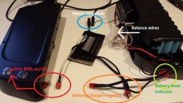
I successfully verified that indeed the BMS mosfets do shutdown if the two wires are open, and when the switch is toggled on (wires short) then the BMS is active!

yay, this is perfect because now I shouldn't get that surge of power to the anderson on the load side. I also made the BMS entirely 100% modular so that it is easy to disconnect/connect as well as replace and maintain. All the connectors are Anderson PP or Deans XT plugs.

What do you guys think?
 

Attachments

  • wiring.jpg
    wiring.jpg
    67 KB · Views: 1,306
Does anyone know if I could use this Philips 48v 80watt lightbulb as a load/drain test?

The bulb is 80w, so that's about 1.6Amps by math. I wonder if it will work.

http://www.ebay.com/itm/4340-Work-Light-Electrical-Vehicle-Sealed-Beam-Light-80W-48V-Philips-Made-in-USA-/261480491799?pt=LH_DefaultDomain_0&hash=item3ce173ab17
 
nukezero said:
Does anyone know if I could use this Philips 48v 80watt lightbulb as a load/drain test?

The bulb is 80w, so that's about 1.6Amps by math. I wonder if it will work.

http://www.ebay.com/itm/4340-Work-Light-Electrical-Vehicle-Sealed-Beam-Light-80W-48V-Philips-Made-in-USA-/261480491799?pt=LH_DefaultDomain_0&hash=item3ce173ab17


Just do this:

http://ypedal.com/Lbd.htm
 
madin88 said:
the graph at 20A (the green line is the outstanding VTC5): http://dampfakkus.de/highamps/523-vs%20lg+samsung.jpg

this makes sense. Internal resistance seems to differ at higher C rates. I wouldn't have thought that. Thanks for clarification!
 
crossbreak said:
madin88 said:
the graph at 20A (the green line is the outstanding VTC5): http://dampfakkus.de/highamps/523-vs%20lg+samsung.jpg

this makes sense. Internal resistance seems to differ at higher C rates. I wouldn't have thought that. Thanks for clarification!

yes, the VTC5s perform well for what they are. I really wanted to buy them. Of course, they cost 40% more than the 25R. But who is running 20A or 8C on the 25Rs? Nobody should be running a cell at it's max C imho. Should buy a more expensive cell and run it at 50-75% of it's C instead.

For me, my max discharge rate for this whole 48v frame mounted pack is 30A. 30A/4p = 7.5A per cell . 7.5A/2500mAH = 3C. This is the maximum I would be pulling out of the 25R. So extra money spent on the VTC5 would yield no benefits in my case.
 
Just wanted to give up a 2-months update on this pack build after about 40 charge/discharge cycles. Wanted to discuss about how this pack is holding up overall in this tight space.

I was initially worried about several issues:

1. Tightness of a lot of things squeezed in, especially with large BMS inside. However, I showed no wear/chaffing through the electrical tape caused by any rubbing or impact from the plastic case. This is good news.

2. I have since un-wrapped all the electrical tape and observed for any cell-2-cell chaffing. I observed, to my surprise, ZERO chaffing, scratches, wears, or knicks.

3. I observed no burnt or loose solders.

4. I have however observed that a couple nickel tabs did slightly bend a bit horizontally by a few mm. What this suggests to me was that, the electrical tape was not holding the pack tight enough, no surprise. But overall, the pack is in excellent condition with no discernible risk of damage due to the shock of bicycle vibration.

I have since made a few more investments into making the pack even safer.

1. I have glued all the individual 4P tabs using hot glue. This has now made the pack a lot more rigid. I didn't do this the first time because I wanted to make sure the cells were good during the first test runs.

2. I have purchased some very high quality 0.3mill thick heat shrink tubing and then wrap the cells over in heat shrink tubing. This tubing was surely a lot more thicker than 4-5 layers of electrical tape. I would say it is equivalent to about 12 layers of electrical tape. But it shrinks to hold the cells even tighter.

I have re-assembled the pack back into the case and everything looks good. Overall, I would say that keeping the batteries nice and tight prevents a lot of movement, which is the sole cause of chafing and rubbing. There was nothing observed after 2 months and 40 cycles of riding where rubbing could occurr.
 

Attachments

  • 20140719_175056.jpg
    20140719_175056.jpg
    50.8 KB · Views: 1,233
  • 20140719_175104.jpg
    20140719_175104.jpg
    51 KB · Views: 1,233
  • 20140720_004801.jpg
    20140720_004801.jpg
    38.8 KB · Views: 1,233
Back
Top