The LiFePO4 Headway cell 38120P TEST REPORT inside

OK, this is going to be a little long, and I'll probably provide more details than anyone is interested in (sorry), but here goes, nonetheless:

Tested one battery as ZapPat recommended, but did it with a wider range, starting at 1Amp and increasing in steps up to 30 Amps:
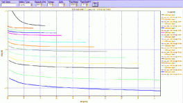
h29-multi_1-30Asm.gif
Higher res view here: http://www.az123.com/E-S/h29-multi_1-30A.gif

The battery tested was one of the lower-middle AH ones; 8.60AH at 8A on the first test.
Came off the charger at 3.88V. Let it sit for about 20 minutes, the battery was at 3.83V on the CBA, 3.812V on my good meter, and 3.810V at the Anderson connectors where my clamp type battery holder plugged into the CBA.

I guess the easiest way to give the results is to use the time I did things as the first element:

5:05 PM: Start test at 1A. 30 seconds into the test the CBA indicated 3.48V and the meter indicated 3.493V. The curve started to flatten in about 6 minutes, got quite flat in 10 min.
5:15PM at 1A, CBA indicated 3.31V, Meter indicated 3.307V STOP.

(I let the battery rest between tests long enough that it recovered as much as it was likely to.)

5:35PM Resting battery is 3.35V on CBA, 3.337V on Meter. Start test at 2A: at about 30 seconds, CBA read 3.29V, meter 3.291V.
5:38PM 2@A curve is flat. 3.28V CBA , meter reads 3.280V. STOP

5:45PM resting 3.34V CBA, Meter 3.329V Start 3A test. 30 seconds into test, CBA is at 3.32V, meter is at 3.329.
5:50PM 3A curve is flat, CBA reads 3.24V, meter is 3.356V. STOP

5:55PM resting CBA= 3.34V Meter 3.326V Start 4A test. @30 seconds, CBA=3.22V, Meter=3.240V
5:58PM 4A curve is flat: CBA=3.32V, meter = 3.234V STOP.

]6:05PM Resting CBA=3.34V, meter = 3.326V. Start 5 Amp test. 30 seconds CBA=3.21V, Meter=3.228V
6:08PM 5Amp curve flat: CBA=3.18V, meter=3.210V. STOP

6:18PM Resting CBA=3.34V, Meter=3.326V. Start 8 Amp test. 30 seconds, CBA=3.12V, meter=3.165V
6.21PM 8A curve is flat; CBA=3.10V, Meter=3.145V STOP

6.27PM Resting: CBA=3.34V, Meter=3.323V. Start 10A test. 30 seconds; CBA=3.06v, Meter=3.118V
6:30PM 10A curve is flat, CBA=3.04V, Meter=3.100V. STOP

6:35PM Resting CBA=3.33V Meter= 3.317V Start 12A test. 30 seconds; CBA=3.02V, Meter=3.085V
6:37PM 12A curve is flat, CBA=2.98V, Meter=3.058V STOP.

6:45PM Resting CBA=3.33V, Meter=3.318V. Start 15A test. 30 seconds; CBA=2.93V, Meter=3.017V
6:47PM 15A curve is flat; CBA=2.90V, Meter=3.001V. STOP.

6:55PM Resting CBA=3.32V, Meter=3.306V. Start 18A test. 30 seconds; CBA=2.87V, Meter=2.976V
6.57PM 18A curve is flat; CBA=2.82V, Meter=2.946V. STOP.

7:03PM Resting: CBA=3.31V, Meter=3.296V. Start 20A test. 30 seconds; CBA=2.82V, Meter=2.927V
7:05PM 20A curve is as flat as it is going to get; CBA=2.76V, Meter=2.908V. STOP

7:11PM Resting.: CBA=3.30V, Meter=3.291V. Start 25A test.... CBA immediately self-terminated test.
(So, Ignore that red 25A test entry on the graph)

Seems like even when you click "OK" to override the suggested limitations based on battery type, the CBA won't let you test; That's what got me thinking weeks ago that it was not working properly at higher currents. But I finally figured out that you can trick it, at least for these short term tests. It might not be safe for a long run, but it seems to work fine like this. I increased the entry of the AH capacity of the battery to 40AH, and lowered the cutoff voltage to 2.2V.

So, retrying 25A:

7:20PM Resting: CBA=3.31V, Meter=3.297v. Start 25A test. 30 seconds; CBA=2.69V, Meter=2.835V
7:22PM 25A curve is as flat as it is going to get; CBA=2.61V, Meter=2.88V. STOP.

7:30PM Resting: CBA=3.30V, Meter=3.284V. Start 30A test. 30seconds: CBA= 2.56v, Meter=2.760V.
7:32PM 30A curve is as flat as it is going to get; CBA=2.48V, Meter=2.713V. STOP.

So, at the higher amp tests, it appears that the CBA is registering voltage quite a bit lower than reality. I think that due to the steep discharge curve, it isn't a huge difference in the actual battery capacity, but I'd guess that they are about 0.1 to 0.25 AH better than my CBA has been saying they are.... Anyone have a better estimate on that based on the info I have provided?

I finished the h29 battery off with a straight 8A test. it had 2.91AH @ 8A left after the individual step tests above. Very close to the end, I tested with the meter: CBA = 2.60V, Meter=2.638V
 
First of all, thanks for posting these results, RLT!

My observations using these results:

- It looks like your CBA has it's own internal resistance of about 7-8mOhms.

- Using these results it still seems that this particular cell has about a 20mOhm DC internal resistance.

RLT: Could you test another cell for me?(or two or three or so... :D ) I want to know if this particular cell is bad, cause it seems this way (we hope anyways!)

Also, here are some test methodology suggestions:
- Firstly, don't test(discharge) the cell for too long for each test current. This is so that we don't introduce too much error resulting from the natural slight discharge curve of LiFePO4. So maybe keep each discharge test to 15-30 seconds or so total.
- Eliminate some of the test currents to limit the total discharge range. Maybe keep 5, 10, 20 and 30 amps tests only.
- After first series of tests, recharge the cell and redo the sequence but this time upside down (30,20,10,5)
- Always start by doing the surface charge drain first until voltage stabilises (similar to what you did before, but maybe try at 0.5C [5A] for 5 or so minutes?)
- To save yourself trouble, only take voltage readings right before you stop each discharge test (so after 15-30 seconds)

And yes RLT, you are right about loosing some Ahs to your CBA'a voltage drop. To estimate how much, lets see:
CBA internal resistance: 8mOhms
W lost at 5A : 5^2 * 0.008 = 0.2W
Wh lost: 0.2W *1.8h[estimated] = 0.36Wh
This explains a fairly large part of your apparent capacity loss.

One important thing to check would be what real currents are being used for these tests? You could use a multimeter to check up to 10 or 20 amps depending on the meter, or use a low value resistor (shunt) to check. Even your watts up or CA with it's own seperate battery pack as a power supply should work for this (or so I gather since I don't really have one yet).

Knowing the real test currents will also change measured capacity (Ah's), but we don't know how much yet.

Good luck and I'm looking forward to other results, RLT!

Also it would be great if anyone else could do this kind of test on their own cells, be it from headway or others! I will collect any data provided and will made a usefull table for all to see and use. The tests could fairly easily be done also with a couple large resistors and two multimeters.

Ciao!
 
Eliminate some of the test currents to limit the total discharge range. Maybe keep 5, 10, 20 and 30 amps tests only.

I actually thought of that after I was about 2/3 of the way through that test.

Thanks for doing the math. That kind of stuff makes my head hurt.

I'll try to do the other things you recommend... eventually anyway.

Even your watts up or CA with it's own seperate battery pack as a power supply should work for this (or so I gather since I don't really have one yet).

I thought I mentioned that before.... I tried that, and somehow the Watts up and the CBA didn't get along at all together. I think the external power to the Watts Up is somehow bleeding through and screwing up the sensors in the CBA.... badly.. I thought about doing it with two cells in series so that I don't have to use the external power, see if that works.. I also have a Cycle Analyst, but I'm unaware of how to use it with single cell voltages... My good multimeter will do 20A but only for fifteen seconds, then has to be off for three minutes. I guess I could use a panel meter and shunt, I have an extra 100A shunt and meter laying around.... somewhere.

Wh lost: 0.2W *1.8h[estimated] = 0.36Wh

Ok, if I'm figuring right, at single cell voltage, that is pretty close to the 0.1AH loss through the CBA that I guesstimated previously. Even taking that into account, most of these things are falling far short of specifications.... (correct me if I'm wrong.)

Could you test another cell for me?(or two or three or so... :D ) I want to know if this particular cell is bad, cause it seems this way (we hope anyways!)
I wouldn't mind, (but shipping back and forth to Canada is a hassle for me.) Maybe Doc Bass could do it. He has a better setup and knows what he is doing a lot more than I do, and he is nearly a neighbor of yours.
------------------------------------------------------------------------------
One little update on cell performance:
I was trying my first discharge test using the Watts Up and a resistor (Two 300Watt light bulbs in parallel ; ≈ 2 Ohms. Draws about .80-.81 amps off a single cell. I thought I was finally going to get over 10AH out of one of these cells, since it stayed above 3.2V for several hours, and kept going at over 3.0V for over 9AH. I figured it would stay well above cutoff voltage for several hours more, but I turned my back for an hour, and when I checked again, it was down to 1.9V, at 9.771 AH .

Was afraid I may have hurt the battery, but I charged it back up and tested it twice at 8A.... Seems to be maintaining the same capacity as the initial 8A check, ±.04AH. So, that's a bit of a relief.
 
RLT said:
Even your watts up or CA with it's own seperate battery pack as a power supply should work for this (or so I gather since I don't really have one yet).
I thought I mentioned that before.... I tried that, and somehow the Watts up and the CBA didn't get along at all together. I think the external power to the Watts Up is somehow bleeding through and screwing up the sensors in the CBA.... badly.. I thought about doing it with two cells in series so that I don't have to use the external power, see if that works.. I also have a Cycle Analyst, but I'm unaware of how to use it with single cell voltages... My good multimeter will do 20A but only for fifteen seconds, then has to be off for three minutes. I guess I could use a panel meter and shunt, I have an extra 100A shunt and meter laying around.... somewhere.
That's why I say "it's own seperate battery pack", meaning not an AC adaptor or anything, cause this will cause ground issues... I'm quite sure this is what is happening.

Of course you could just use your multimeter, and limit each load test to 10 or so seconds.

Could you test another cell for me?(or two or three or so... :D ) I want to know if this particular cell is bad, cause it seems this way (we hope anyways!)
I wouldn't mind, (but shipping back and forth to Canada is a hassle for me.) Maybe Doc Bass could do it. He has a better setup and knows what he is doing a lot more than I do.

I meant here that I would like to be sure that the 20mOhm DC resistance is what most headway cells are, and that this one is not just an exeption. I have yet to receive any nice lithium cells to test myself :cry: , but in a couple weeks I'll have a new Ping pack to test and let everyone know about it.

I wish someone here could do this type of simple test on an A123 cell... come to think of it, doesn't doc have some?
 
OK, that didn't work out very well. I tried to double check the CBA current draw (set at my usual 8A) through my good meter in series, and the test very quickly self terminated just as it did earlier with the Watts Up in parallel.

I guess Mr. CBA just doesn't like having his results questioned.

Who was the guy that postulated that merely testing something makes the results change compared to what the results would have been were they not being tested???? Schrödinger?

But for the three seconds the test did run, there was only a .08A disagreement between the CBA and the meter.
 
RLT said:
OK, that didn't work out very well. I tried to double check the CBA current draw (set at my usual 8A) through my good meter in series, and the test very quickly self terminated just as it did earlier with the Watts Up in parallel.

I guess Mr. CBA just doesn't like having his results questioned.

Who was the guy that postulated that merely testing something makes the results change compared to what the results would have been were they not being tested???? Schrödinger?

But for the three seconds the test did run, there was only a .08A disagreement between the CBA and the meter.

Humm, maybe the added resistance of the meter / watts up is too much... which almost doesn't make sense because it is similar to any cell's internal resistance. Maybe too much inductance added make Voltage spikes that the CBA doesn't like (it surely uses PWM, so load inductance would affect it). Mr CBA does seem very secretive, that's for sure! :lol:

At any rate, at least you saw that it was not off by too much while it did work!

I'm still curious to see if all headway cells have similar high internal DC resistance... but no rush RLT.
 
Somehow I missed that post when I posted right after it.

That's why I say "it's own seperate battery pack", meaning not an AC adaptor or anything, cause this will cause ground issues... I'm quite sure this is what is happening.

I WAS using a separate battery pack, not an adapter.

I meant here that I would like to be sure that the 20mOhm DC resistance is what most headway cells are, and that this one is not just an exeption.

OH! OK, Sorry. Me No Comprendo Canada Talk Very Good ;)

I can do that. How about I run another couple of multi- tests: on the highest AH battery and the lowest AH Battery? That ought to give a good spread... The one I did before was sort of in the low end of the middle range.

I might be able to get both done in the next 36 Hours.
 
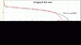
OK, Here is the results of the multiple current tests of the best and the worst of the batteries that I have tested so far:
#h20 is the best, having given 9.47AH @ 8A on the first charge; (There were a couple of batteries that I got higher AH ratings, but they were tested at lower amps, so I decided to go with #20 for this comparison)
#h27 is the worst having given only 8.31AH @ 8A on its first test.

I couldn't trick Mr. CBA into measuring @30 amps this time; He must have been watching as I typed in last time about how I tricked him. Devious, thing, he is. :twisted: :roll:
The highest he would consent to test tonight was 29Amps. :( I've got him unplugged now and covered up, so he won't be able to see what I'm typing about him this time ;)

This time, I tested each cell at INCREASING amperage. They are back on the charger now and will be tested at decreasing amperage next time.

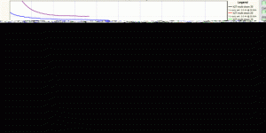
First, let me post a graph showing BOTH #20 & #27 at 5, 10 and 20 Amps:
(The numbers in purple are meter readings at the battery terminals, which are apparently more accurate than the CBA voltage readings.)
h20_27_5-10-20.gif
Well, that thing about the better capacity battery having lower voltage at the same amps reflects the original 8A tests:
20-27_8A.gif
I noticed a similar behavior on one of the more recent 8A tests I ran, where the battery dropped to 3.07V almost immediately, yet still gave a fairly respectable 9.17AH.

Here is the test of #20. When the CBA refused to do 30Amps, I did it at first, 25A, then 28A, then 29a, which was the highest I could get it to work..... So there are a few more steps than Zap Pat requested, and that is the reason that I did the first comparison graph above at only 5, 10 & 20 amps, so that the extra two steps wouldn't skew the 29A performance:
h20up.gif
Meter readings taken at the battery terminals for this test were:
3.209V @ 5A
3.101V @ 10A
2.896V @ 20A
2.804V @ 25A
2.778V @ 28A
2.746V @ 29A
--------------------------------------------------------------------------------------------------------------------
Here is the graph for #27 (the lowest AH one)at the various amperages:
h27up.gif
Meter readings taken at the battery terminals for that test were:
3.330V @ 5A
3.132V @ 10A
2.961V @ 20A
2.824V @ 29A
----------------------------------------------------------------------------------------------------------
More to come.
 
OK... Same basic setup, same two batteries, the best and the worst (so far). DECREASING Current this time; 30A to 20A to 10A to 5A
(Yes, I did manage to convince Mr. CBA to test at 30A this time.)

Here is #h20... the better AH battery:
20down.gif

Here is #h27... the worst AH:
27down.gif

As the following combination graph of the increasing and decreasing current tests indicates, the direction doesn't matter much; Only even noticeable at the lowest current:
27UpDn.gif

I finished off #h20 at a constant 15 amp draw, manually cutting it off at 2.5V according to the multimeter rather than the CBA. Coincidentally (?) at 15A the meter indicated almost precisely 0.10V higher than the CBA digital display. After the above tests, h20 was able to give another 8.15AH before reaching the metered 2.5V cutoff voltage ... If left to itself, the CBA would have shut off at 7.77AH... For a differential of 0.38 AH... A little more significant difference than I expected. The battery got nicely warm at 15A... Just about perfect to warm your hands on a cold day, but not enough to cause alarm. (If I could find one of my two thermocouples, I could tell you what the actual temperature was.)

Finished off #h27 at a constant 10A. At 10A the meter indicates about 0.065V higher than the CBA digital display; This cell gave another 6.78AH after the above tests... The CBA would have cut it off at 6.61AH.. For a differential of .17AH... Closer to what I estimated the other day when we were discussing this. At 10A the battery was warmer than the ambient, but not much... My laptop computer keyboard is warmer at the moment.

I"m going to run some more tests to see if I can develop an algorithm.. or at least a chart, to set an offset for lowering the CBA cutoff voltage so that I can get automatic cutoffs that more accurately reflect the true capacity ..... But despite feeling a little more positive about the capabilities of the Headway 38120Ls, even allowing for the largest differential, they still fall short of their claimed 10AH capacities.
 
WoW!! Great tests there, RLT!

These results confirm your previous tests.

I think it is now fairly safe to say for sure that the headway cells, model 38120L, have a measured internal DC resistance of about 17 mohms per cell. Headway claim that these cells have an internal AC impedance of 3 mohms, and have no DC resistance specs. From other battery specs I've seen around, it would be very unlikely that these two properties be so far apart. Examples from other cell data sheets (these are theoretical, and have have not been tested as the headways YET):

Valence Technology Lithium Ion battery - IFR26650 Powercell - 2.4Ah, 20A cont. discharge : 8 mOhm AC impedance, 12 mohm DC resistance
LiFeBatt 10Ah cells: 6 mOhm AC impedance, DC ??
A123Systems lithium ANR26650M1 cell - 2.3Ah, 70A: 8 mOhm AC impedance, 10 mohm DC resistance
[funny note about the A123 here: the datasheet discharge curves would indicate more like 16 mohms DC resistance! :? ]

I would be really informative to everyone if we could collect similar info for other packs and/or cells - and it is easy to do, even without a battery analyser we can geta good idea!

WHY is this important to know? This is what produces your dreaded voltage sag, and thus power loss, specially under heavy load!

RLT said:
I finished off #h20 at a constant 15 amp draw, manually cutting it off at 2.5V according to the multimeter rather than the CBA. Coincidentally (?) at 15A the meter indicated almost precisely 0.10V higher than the CBA digital display.
[...]
I"m going to run some more tests to see if I can develop an algorithm.. or at least a chart, to set an offset for lowering the CBA cutoff voltage so that I can get automatic cutoffs that more accurately reflect the true capacity .....

Just use ohm's law to adjust your CBA results, since we have measured it's resistance to be around 7 mohms. So you loose 0.07volts per 10A drain (0.007ohm * 10A), just as you have noted in your tests. (so 0.14V at 20A, 0.21V at 30A...)
Remember also that you are not just loosing Watt-hours to this early cutoff phenomenon induced by your CBA's added resistance, but also from the accumulated voltage error over the whole discarge curve. So at 10A you are loosing another 0.007ohm * 10A * 10A = 0.7W during your whole discharge period. Lets say this is 50min, or 0.83 hours, so you loose another 0.7Watts * 0.83 hours = 0.58Wh lost right here due to the CBA's voltage error! Add that to your other loss due to low cutoff, and your cells look more up to spec capacity-wise (in Ah's) on paper at least.

But despite feeling a little more positive about the capabilities of the Headway 38120Ls, even allowing for the largest differential, they still fall short of their claimed 10AH capacities.

They are a bit better after adjusting for the loses produced by your CBA's low readings, but so far still a bit under par for sure. IMHO the DC resistance of these cells is more of a problem, since this causes a large loss of usable energy in the end, as well as degraded performance at high discharge rates.

Finally, we should remember that any cell with high internal DC resistance would rob us of usable Watt-hours because of the resulting voltage sag, so choose your cells and packs wisely, everyone!
 
There should be a standardized system of LiFePO4 Specifications. Here is how Sandia National Laboratories reported the specs. for LiFeBATT Cells. If we could get independent reports for all Mfg. it would be great to make a master chart of all the various offerings and their independent laboratory reports, no matter what protocol was used.

In this paper the performance of the Li-Ion LiFeBatt cell was measured using a number of tests including capacity measurements, capacity as a function of temperature, ohmic resistance, spectral impedance, high power partial state of charge (PSOC) pulsed cycling, pulse power measurements, and an over-charge/voltage abuse test. The goal of this work was to evaluate the performance of the Iron Phosphate Li-Ion battery technology for utility applications requiring frequent charges and discharges such as voltage support, frequency regulation, and wind farm smoothing. Test results have indicated that the LiFeBatt battery technology can function up to a 10C1 discharge rate with minimal energy loss compared to the 1 h discharge rate (1C). The utility PSOC cycle test at up to the 4C1 pulse rate completed 8,394 PSOC pulsed cycles with a gradual loss in capacity of 10 to 15% depending on how the capacity loss is calculated. The majority of the capacity loss occurred during the initial 2,000 cycles, so it is projected that the LiFeBatt should PSOC cycle well beyond 8,394 cycles with less than 20% capacity loss. The DC ohmic resistance and AC spectral impedance measurements also indicate that there were only very small changes after cycling. Finally, at a 1C charge rate, the over charge/voltage abuse test resulted in the cell venting electrolyte at 110 °C after 30 minutes and then open-circuiting at 120 °C with no sparks, fire, or voltage across the cell.

Table 2. LiFeBatt Summary Test Results.
TestCell #1Cell #2Cell #3Initial Capacity C/2 (Ah)9.619.889.81Initial DC Ohmic Resistance (Ohms)0.00360.00370.0033Initial AC Spectral Impedance ESR (Ohms)0.0041NANACell Power and Energy Density at 10C1 Rate (W/l, Wh/l, W/Kg, Wh/Kg)NANA1,068, 116, 653, 71Cell Capacity and Recharge As A Function Of Temperature (Ah @ 35, 25, 0, -20, -30, and -40CNANA10.41, 9.81, 7.26, 6.34, 4.67, 0.27Cell Utility Cycle-Life PSOC Test (Cycles, % Capacity Loss) 8,394 / ~15%NANAFinal DC Ohmic Resistance and Spectral Impedance (Ohms, ESR)0.0042NANAFinal AC Spectral Impedance ESR (Ohms)0.0037Final Capacity Test C/2 (Ah)8.91NANAHybrid Pulse Power Test (Charge/Discharge Power (W) at 50% SOC)NANA198, 331Over Voltage/Charge Abuse Test (Vent Temp, Max Temp, Fire Y/N)NA110°C, 160°C, NNA

4. SUMMARY
Table 2 provides a brief summary of the test results. These results indicate that the LiFeBatt cells meet the manufacturers specifications in capacity, internal ohmic resistance, max power, and specific energy. The temperature performance at 35, 25, 0, -20, -30, -40 °C show that both discharge capacity and recharge voltage are significantly affected by temperature especially at temperatures below -20 °C. From -20 °C to 35 °C the capacity will increase by about 0.8% per 28°C. At temperatures below -20 °C the capacity drops dramatically to just 3% at -40 °C. The 10 second pulse power capability values can be used to scale up for larger pulse power applications and show power levels of 325 W/cell on discharge and 300 W/cell on charge at 50% SOC. The Utility PSOC pulse cycle test results after 8,394 cycles suggests that the LiFeBatt cells will PSOC pulse cycle up to the 4C1 rate for utility applications. Performance degradation was identified by capacity fade (10 to 15% loss - based on 9.61 or 10.14 Ah initial capacity) and by the increase in end of charge voltage during high power and medium power pulses. Based on the slow trend of capacity fade, the test cell should PSOC pulse cycle well beyond the 8,394 cycles tested before reaching 80% of initial capacity. This assumes that there will be no premature failure mechanisms that terminate life early. The ohmic resistance measurements and spectral impedance measurements before and after the PSOC pulse cycling have indicated only a slight increase in ohmic resistance and a slight drop in ESR for spectral impedance. The ohmic value increased from 3.6 to 4.2 mohms, while the AC spectral impedance ESR value decreased from 4.01 to 3.74 mohms. This is a very minimal change, if any, and indicates no similar degradation as seen in the LiCoO2 materials where increases in all of the impedances measured occur, and in some cases the formation of another passive film can form. Finally, the over charge/voltage abuse test indicated that the LiFeBatt cell can fail without fire, or damage to other external systems if those systems can handle the 160 °C max temperature and electrolyte venting.

Best Regards,

Don Harmon
 
Just use ohm's law to adjust your CBA results, since we have measured it's resistance to be around 7 mohms. So you loose 0.07volts per 10A drain (0.007ohm * 10A), just as you have noted in your tests. (so 0.14V at 20A, 0.21V at 30A...)

OK, Cool. I figured someone would point out that there was an obvious correlation like that. My brain just doesn't work that way.. I have to discover things experimentally:

Touch the tip of the soldering iron with my finger .. Ouch! That's hot. Touch it again, Ouch, that's hot. Hmm. Wonder if there is some correlation. Touch it again. Ouch! Eureka! a truth! :idea: Now lets see if it works the same when unplugged. ;)
 
Nice tests so far RLT! :D

For me its obvious that you should use the shortest and thickest wires to your CBA to get the best accuracy in voltage cutoff.

Also, I think it is save to say that headway's productionline is not finetuned by now. What leads to different powder-layer thickness. The thicker the powder, the higher the capacity but also a higher inner resistance/voltage drop is the result. Your graphs are reflecting the same behaviour.

I hope headway can sort that out soon, otherwise there will be some complaints.
-Olaf
 
olaf-lampe said:
For me its obvious that you should use the shortest and thickest wires to your CBA to get the best accuracy in voltage cutoff.
-Olaf
Yup, this sounds like it may be the cause of your problems. I just thought of it too yesterday night around one in the morning, when I read your CBA prOn posting: http://endless-sphere.com/forums/viewtopic.php?f=2&t=278&st=0&sk=t&sd=a&start=300#p83327 (nice post by the way!).

I wonder if this will explain the whole 7 milli-ohms, though?
 
I just received the replacement cells for the two (out of 100) which wouldn't produce a stable voltage, without having their ends strongly pressed together, which I got with the initial shipment. These replacements were sent to me at no extra cost and check out OK. I just want to say that I'm very pleased with the prompt communication and high level of customer service which I've received from Victoria at Headway. :)
 
Did you deduce a new value for the ESR yet?

Have you determined how long a 10C draw can occur?

thanks,

Mike
 
You should be able to trick the CBA into current as high as 40 amps. It basically will let you do 1 ah and less at 150w of power but for over 1ah it rated for only 100w. It figures out which one you can do based on what you enter in capacity. I had my thermal and shut down a couple times but if your weather is cool you might be able to go over 1ah. I have issues with mine over 35a so be careful!

Also if you really want accurate tests you can do a remote voltage sense with the CBA removing that little jumper by the input wires:

http://www.rcgroups.com/forums/showpost.php?p=4271677&postcount=10

Again try all this at your own risk and most of all keep testing!!!
 
flip_normal said:
I just received the replacement cells for the two (out of 100) which wouldn't produce a stable voltage, without having their ends strongly pressed together, which I got with the initial shipment. These replacements were sent to me at no extra cost and check out OK. I just want to say that I'm very pleased with the prompt communication and high level of customer service which I've received from Victoria at Headway. :)

Hi Flip - Any chance of you testing these replacement cells for internal DC resistance using two or three different loads? It would give us an idea if the cell batches change much or not in caracteristics. The first cells tested a while ago seemed to have about 8-9 milli-ohms internal resistance, but RLT's have more like around 17 milli-ohms DC resistance which is not too good for such large capacity cells.

Thanks!
 
Here ya go Zap.

Charged both cells CC/CV to 3.65V then discharged each cell at 2.5A for three mins to take off the surface charge.

Results:

Cell 1: 3.10V@12.5A : 3.17V@7.6A : 3.27V@2.5A
Cell 2: 3.10V@12.5A : 3.17V@7.6A : 3.27V@2.5A

Both cells the same. :) Wanna do the math? I gotta scoot. :D

Edit: That seems to give 3 results; either 14, 17 or 19 mohm :? right?
 
I have a dumb question for y'all.

I'm new at this, but I am looking to build my own battery for my Ebike if possible.

I'm a steam engineer, not an electrical one. Blasted electrical stuff!!! :mrgreen:

I have noticed the $700 48v/20ah LiFePO4's on Ebay, but the discharge rates are a little low for what I want in my Ebike. I want to build one for a Crystalyte 5303, using a Kelly 100amp/50amp cont. regenerative controller.

Anyway, with the nice programable controller, and low voltage cutoff, do I really need a seperate BMS?

From what it appears, I can program the Kelly controller to have amp rate limits and LVC to prevent battery damage. If I just hook two 16 cell packs in parrallel to get 20ah, would I have problem with balancing?

My plan would be to just hook a 2-3amp smart charger to the leads, and let it go on its own, for charging.

Also, has anyone in the USA ordered a 32-cell set of these?

With shipping and any duties, how much did you get them for?

Sorry for all the questions, but I like these cells. They are affordable, and have better disharge capacity compared to others I've seen.
 
flip_normal said:
Here ya go Zap.

Charged both cells CC/CV to 3.65V then discharged each cell at 2.5A for three mins to take off the surface charge.

Results:

Cell 1: 3.10V@12.5A : 3.17V@7.6A : 3.27V@2.5A
Cell 2: 3.10V@12.5A : 3.17V@7.6A : 3.27V@2.5A

Both cells the same. :) Wanna do the math? I gotta scoot. :D

Edit: That seems to give 3 results; either 14, 17 or 19 mohm :? right?

Thanks flip for the tests! Maybe the DC resistance differences are due to taking the readings still not far enough into the discharge curve? (2.5A for three minutes is only just above 1% capacity of these cells after all) Also make sure you take the readings twice on each cell - meaning that it's good to do the whole sequence twice in a row just to be sure.

So:
Discharge surface charge until voltage starts getting flat (maybe around 5-10% of the capacity?);
Now take the cell voltages at high current, medium current and then low current discharges;
Then again test at high current, medium current and low current.

Even with the different results you got, these replacement cells seem to be pretty much the same as RLT's. Has anyone ever asked Victoria or anyone else at headway about this abnormaly high DC resistance for cells supposedly rated for high discharge rates? From what I've gathered they should be at least half the resistance of what we are seeing... :(
 
THere was a break in production I believe recently, I am waiting for the first of the new batch to be shipped. If the new ones arn't any better then we shall know the cells real limitation I guess. I'll let you all know when they arrive...
 
about the LVC, you should follow the thread on the BMS that gary and fechter have just finished. initially bob had developed the idea of having LVC capable of monitoring each cell, which seems to me to be the most essential part of any BMS since even just a brief cell reversal can destroy a cell which could otherwise be capable of thousands of cycles. bob deserves a lot more credit for this than he has received, imo. one of my favs here.

why not join the headway group buy and save a ton of money on the shipping? joshua seems a straight up sorta guy who just ran into the lifebatt problem which seems to have followed us to this thread. none of the stuff quoted by don is of any relevance to understanding the headway imo, and was just trash on this thread. it would be nice if you just took a cell or two and sent them to someone with a CBA so we could compare, worth more than a thousand sale plugs.

i agree with the 17-19mohms from those few measurements, and the 21mohms originally. but the numbers i got originally from RLT's CBA graphs seem to indicate that 30-40+mohms is to be expected over the flat part of the discharge from his cells and i posted up some more numbers on his last batch over on the headway group buy yahoo group, ranging from a low of 18mohm for #27 to a high of 34mohm for #25, with lower resistance characterizing the higher current discharge rates. and internal resistance climbing rapidly close to the end of the total capacity.

it would be useful if there were more of the CBA's around and all the cells could be characterized, the data would be useful in grouping cells together in packs so their performance was matched to reduce balancing, and the cells could then be evaluated later to establish how and why their performance degrades, and as i said before that would be useful to collect and saved in data files here on ES.

i saw there was guy with a buncha CBA's at some closeout store on ebay, but he wanted more than west mountain radio. maybe we could organize a group buy of his CBA's and offer him something like $60/unit for all his analyzers and then split them up around the country for people to share. or maybe someone can hack it and we can build clones, but i doubt if we could build them cheaper than $60.

i wanna thank doc for starting this thread, even though i am at odds with everyone over the internal resistance issue. i think victoria should be telling her bosses to have the manufacturing engineers look at the variability of internal resistance, before they sell a batch of poor performers and get a bad reputation, and mr ping too.

thanks, dm
 
Back
Top