The Megapower 960SR High end Charger/discharger/cell testing

Doctorbass

100 GW
Joined
Apr 8, 2007
Messages
7,501
Location
Quebec, Canada East
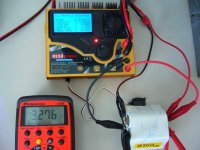
From a couple of month ago, I have been talking about this charger that i bought and that i reqally appreciate.

here it is:
MP960SRV2b(1).jpg


And combining this 1-12cells balancer for A123 and lipo, that make the perfect combo to play with your battery!

MEGPOWERLC01.jpg

960SRLCB12S_cr.jpg


spec:

MAIN FEATURES

1-12 cells - A123
1-30 cells - NiCd & NiMH
1-12 cells - Li-Po & Li-Fe
1-12 cells - Lead-Acid
1-8 cells - NiCd & NiMH TX-RX
Charge Current : max 10A(180W)
Discharge Current : max 5A(50W)
Internal resistor measurement
Capacity measurement


Specifications:

Input voltage 11-15V DC
Battery type & cells 1-30 cells-NiCd & NiMH battery
1-12 cells-Li-Po & Li-Fe battery
1-12 cells-Lead-Acid battery
Battery capacity 100-20000mAh
Charge current 0.1~10.0A adjustable (2C rate for Li-Po battery)
Charge methods Automatic, Normal, Linear, and reflex
Charge termination Peak detection & zero delta V for NiCd & NiMH battery
constant current / constant voltage for LiPo/Pb battery
Delta Peak Sensitivity 0-25mV adjustable
Trikcle charge current 0-500mA ONLY for NiCd & NiMH battery
Discharge current 0.1-5.0A adjustable
Discharge curtoff voltage 0.1-1.1V per cell NiCd & NiMH battery
2.5-3.7V per cell ONLY for Li-Po battery
Temp cutoff 10-65 C(50-150 F)
Cycle count 1-10 cycles
Cycle cool-off delay 1-30 minutes adjustable
Battery memories 10 memories
Display type 8-Line, 21 character graphical blue backlit LCD
Case size 156.5mmX143mmX55.4mm
Weight 740g


For around 200$, that become very usefull and a great tool to build or test your own battery pack.

I dont really use it to cgarhe my ebike pack, but i could

The real reason why i bought it instead of CBA is that it can charge, cycle and balance the battery. The CBA can't

I really love it and i wouldn't be able to test with great accuracy my dewalt pack without it!

Couple of member bought it and seeme to be satisfied.


I would recommand this great tool for every people that need to test or charge cells with great acuracy :wink:

Doc
 
A low priced link for both would be very much appreciated.
 
Mod for: -- 4 wires volt sensing method --

When i use the cahrger, like all other battery charger, i observed something that can be ameliorated and that will increase the measurement and charging acuracy.

The problem to solve is about the resistance of the wire between the charger output and the battery terminal.

Usually, the charger LCD will display a wrong voltage. if you compare the voltage directly on the battery tab and the that you do the same on the cahrger terminal, the voltage is different! it is normal due to the resistance of the wire.

As you charge or discharge with high current, the voltage error will increase.

Now, you wonder: WHY it is so important to get the exact voltage and to have that accuracy ?

let me explain:

Current that circulate thru the wire is the same at every point in that circuit.. BUT voltage isn't!!

The difference is that if you do some measurement using it, they will be not acurate and the voltage that is used as the threshold for the HVC and LVC cut point (2.9 and 3.75V for LiFe) will not be exact.

In this case, when the charger will read 2.9V for the LVC, the real battery tab reading could be around 3 or 3.050V and will prematurely cut the discharge process. with the 4 wires voltage sensing, the charger will cut later and let you to measure more mAh that will give you the real capacity of the battery.

Also, when measuring the internal resistor, the value will be corrected and the resistor of the wire will not influence the measurement.

Without the 4 wire volt sensing,
The V error increase if you often change the wire between the cahrger and the battery for exemple to allow you to connect different battery type...etc.. their resistance is not the same...

So I decided to mod my charger to allow the best acuracy i can get with it and to avoid capacity measurement error.

In the pic below, i isolated the ch2 output banana plug terminal to be able to use these terminal for the voltage sensing.
this chanel 2 is really not usefull if you dont use it for RC stuff. this ch2 is a second AUX output to let you to charge the RC receiver battery pack.... :roll:

You will see in the pic that i painted two black arrow in the PCB. they indicate the trace to cut and to redirect.
these arrow are on the ch1 red and black output you will see that when i took the pic, i only had one trace cutted. the trace on the - needed to be cuted too.

BUT THESE TRACE NEED TO BE CONNECTED.
in case where these sensing trace could be not connected, the processor could compensate and rise the voltage output to the max like 60V!! so it is important to protect that to avoid it could happen.

I've put a 1k resistor on both side of the trace to allow a current to pass to give a V info to the processor in ANY case.

This resistor will let the charger to work normally even if you dont connect the V sensing wires. When you will use the sensing wire, the current will pass thru them and will bypass the resistor.

ex of 4 wire sensing
(2 wire have the current to the load and 2 other sense and send back the voltage feedback to the unit to be controlled)
T165Fig10.gif


I isolated and connected them differently to sense the voltage.

The internal processor of the charger have V input thru an op-amp that indicate to it the voltage output to let it to correct. it is the Voltage feedback from the output ch1 to the processor.

Normally these little pcb trace goes directly to the banana terminal output. i decided to re-direct them to the old ch2 female banana plug on the PCB and i've isolated them from teh rest of the old ch 2 output circuit.

more pics soon
 

Attachments

  • 4 wires probing method_1024x768.jpg
    4 wires probing method_1024x768.jpg
    133 KB · Views: 2,064
  • P1030809_1024x768.jpg
    P1030809_1024x768.jpg
    165 KB · Views: 2,059
DIY

-first, cut/isolate the trace indicated by the black arrow (they are very small and they are the one that gors to the large PCB pad that hold the banana plug.)

-Remove the green varnish and jump the trace cutted with 1k resistors that you will solder.

-isolate the ch2 (+) and (-) banana plug FROM THE REST OF THE PCB COMPONENT. (cut a circle around them on both side of the PCB)

-they are now isolated from their old ch 2 circuit.

-solder a wire between the ch2 (-) plug and the little trace you cutted on the ch1 (-) terminal. the wire need to be on the other side of the resistor.. not on the side of the ch2 (-) terminal, but on the side that goes to the processor.

-do the same with the (+)


When finished, you shuold be able to observe a voltage difference when you try with or without the 2 aditional wire for sensing.


I recommand that you should NEVER FORGET TO DISCONNECT THEM FIRST! (dont disconnect the main ch1 output while the sensing wire are connected... )

Enjoy!

Here are some pics of the mod that i did:
 

Attachments

  • P1030817_1024x768.jpg
    P1030817_1024x768.jpg
    149 KB · Views: 2,026
  • P1030819_1024x768.jpg
    P1030819_1024x768.jpg
    135.6 KB · Views: 2,023
  • P1030823_1024x768.jpg
    P1030823_1024x768.jpg
    169.7 KB · Views: 2,016
  • P1030805_1024x768.jpg
    P1030805_1024x768.jpg
    125.5 KB · Views: 2,018
All I can say it's about #$@%n time they should produce these with 4-wire sensing, I've been waiting forever.
thanx yet again for your public service to the cause.
I don't have the guts or the deep wallet willing to take the risk of cracking open a new toy to embark on a steep learning curve like you & many others do for everyone's benefit.
Thank you & this forum many times over, even just having pictures to know what to expect helps a lot to minimize the risk of damaging something.
 
Hey doc

I had the courage to do the mod yesterday.

-mah capasity after charge & discharge has stayed roughly the same.
-mOhms resistance acuracy has increased it seems.. i have cells that i charged before and after the mod ... before 25 mohms after mod .. showing 10-12ohms ..pertty big acuracy difference.
-voltage difference .. seems to be in the .10 +/- range..


HVC & LVC

I also wanted to verify this .. what is your charger capasity set at .. i put mine to 90% & not 100% anymore...
after checking it with a multimetter when set at 100% i've found the charger peak the battery to about 3.85v!!.. after turning is down to 90% .. it goes to approx 3.78V .. which is ok i guess

Should i be putting it a lower percentage, did you also have the same problem, what should be the peak voltage the charger should peak the battery at?

Just wanted to confirm does everything seem normal as compared with your charger?..

thanks
steve
 
steveo said:
Hey doc

I had the courage to do the mod yesterday.

-mah capasity after charge & discharge has stayed roughly the same.
-mOhms resistance acuracy has increased it seems.. i have cells that i charged before and after the mod ... before 25 mohms after mod .. showing 10-12ohms ..pertty big acuracy difference.
-voltage difference .. seems to be in the .10 +/- range..


HVC & LVC

I also wanted to verify this .. what is your charger capasity set at .. i put mine to 90% & not 100% anymore...
after checking it with a multimetter when set at 100% i've found the charger peak the battery to about 3.85v!!.. after turning is down to 90% .. it goes to approx 3.78V .. which is ok i guess

Should i be putting it a lower percentage, did you also have the same problem, what should be the peak voltage the charger should peak the battery at?

Just wanted to confirm does everything seem normal as compared with your charger?..

thanks
steve


Hi Steveo,

There is no big difference with capacity measurement results and more diference with the miliohm like tou got. But about Wh measurement (only with logview software) when the main 2 wires are too long or too small, the V difference will change the Wh reading cause the volt reading that is lower without 4 wires will change the current x voltage x time (Wh)
I got around the same miliohm results difference than you. so it's ok.

About the % of capacity, this parameter is the max that you allow to be charged on the cell. I've never used it. I keep it to 120% in case where i could have a cell that have xtra capacity than nominal.

This charger is very smart. analysing the current drop at the end of charge, it will stop the charge process at a given current. the end charge is not set by the max mAh seting but by the current drop at the end of charge.

Also, if you have a cell lithium cell that is too close to the normal lvc limit voltage, it will begin the charge at a low current even through you set the current to higher value.(it protect the cell from bad setting.)

the max mAh setting is to allow you to get xtra cell life by charging it to lower % of capacity.

But personally, i always use this charger to test cells , so i need to know the max capacity.

Doc
 
Hey doc

good to hear i did everything properly :D ...

i will start my match asap :D

-steve
 
today i received my 12V 29A +/-10% V adj I ordered from ebay to supply correctly my megapower. that work great.. very stable, quiet and strong.

I forgot to mention something, NEVER disconnect the main 2 out while the sense wire are still connected to the pack when the charger is running!.. this could dammage the power supply. Mine just blown the 20A fuse :shock:

Bit this beast is VERY strong too!! i just replaced the blown one and it work againno smolw.. no problem!


You know that THIS charger IS the MOST COMPLETE AND VERSATILE CHARGER YOU CAN BUY!!

No other can do all these features in one box: internal resistor measurement, 12s PC RS-232 plug to use with logvier, graph display LCV, 180W charger 50W discharge, cycling, LiFe /A123 full support......... THIS IS THE ONLY ONE !!

Doc
 
I've got to say, I don't like mine very much. The balancing feature is way too slow for me, even on 1p a123 packs it can take hours. Mines getting very little use, even my homebuilt balancer is far easier to use.
 
That is a nice but gutsy mod.

nice power supply 29 amps is that gonna be too much for the mega ?

too bad that can't be used to charge my set up i agree that is very complete charger. as far as it taking for ever to charge isn't that a sign of unbalance pack?

I'd be glad just to use the charger. I just conerted a pc power supply but it is only i think 10 amps. I am going to convert another one that i have lying around that is 17 amps can't wait to try that more.

efreak
 
the balancing feature of the LCB-12s is slow i agree, but mine is more used to monitor each cells. i've built a cable that disable the balancing effect and just allow me to see each individual cells voltages. the LCB12s is balancing to 70A and the Hyperion LBA-10 is 250mAh. that's alot better, but you need two of those because they are max 6s.


About using a PC power supply, be carefull when using the 12V outputs. you absolutly need to put a load on the 5V output too because the 12V and 5V usually need to share the same load value to regulate the 5V output. the 5V regulation does regulate the 12V too. so put at least a 25W resistor on the 5V to not blow the power supply by just using the 12V out.

read on the web about that.

i've blown mine that had a 21A at 12V because i forgot that.

Doc
 
i think i used a 10 watt one on the previous pc ps. You are suggesting i use a 25 w on my next one ? i will thanks i have a little bigger ps from an older scrap pc that wil be converted next.

efreak
 
Doc, how did you disable the balancing feature? Its probably a good idea, since it interferes with my other balancers function, but monitoring cell voltages is nice..
Is it possible to stop the balancer from turning itself off when it feels like it too?
 
Jozzer said:
Doc, how did you disable the balancing feature? Its probably a good idea, since it interferes with my other balancers function, but monitoring cell voltages is nice..
Is it possible to stop the balancer from turning itself off when it feels like it too?

to disable the balancing feature, all a flat cable with 24 wires (DB25 parallel port style) with a connector at the end and with the other end soldered to the base emetter of each cell surface mount transistor on the balancer board. when you plug a bloc with pair shorted, each 2 wire become shported together and dissable the balancing fonction.

The key is to short each cells channel transistor.
see pics

Doc
 

Attachments

  • P1040021.JPG
    P1040021.JPG
    57.5 KB · Views: 2,834
  • P1040023.JPG
    P1040023.JPG
    94.7 KB · Views: 2,832
  • P1040024.JPG
    P1040024.JPG
    52.5 KB · Views: 2,830
  • P1040025.JPG
    P1040025.JPG
    69.2 KB · Views: 2,829
  • P1040030.JPG
    P1040030.JPG
    78.5 KB · Views: 2,829
  • P1030340.JPG
    P1030340.JPG
    88.9 KB · Views: 2,829
  • P1030342.JPG
    P1030342.JPG
    108.3 KB · Views: 2,827
Thanks Doc, i'll have a go at that this week:)
 
Back
Top