• Hello ES! We could use some help to get us past the finish line on building the new knowledgebase for the forum.
    Can you donate? Please see our fundraising page. Thank you!

Trail Crosskart build

regularGuy

New here
Joined
Mar 8, 2026
Messages
11
Location
USA
I am in the planning phase of building my first Crosskart. It will be based on the VF1 chassis designed by KJ Raycing. I was initially going to use an engine out of a Yamaha Raptor, but I started looking into electric and decided it would be a better fit. I have been all over the forums and watched a ton of videos on YT including the James Biggar build. All that being said, I still have some general questions and would appreciate any constructive feedback on my plans.

The Battery -
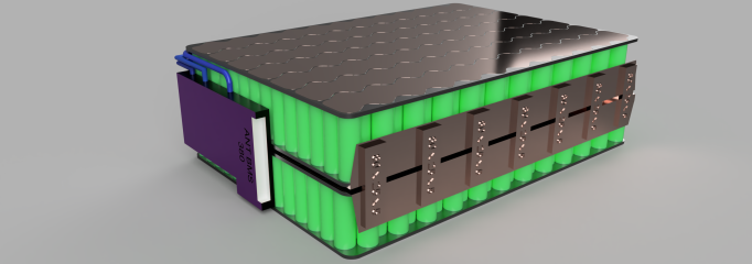
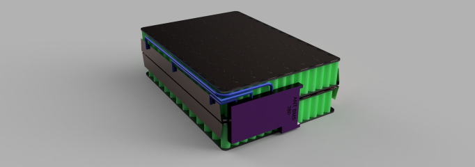
Battery_Final_Assembly_2026-Feb-26_01-57-46AM-000_CustomizedView51279858782.pngBattery_Final_Assembly_2026-Feb-26_01-37-00AM-000_CustomizedView31041507100.png
Layout: Above are a few renders of the layout I am planning. The 7 copper bars connecting the two packs together would most likely be mesh or something flexible so I could fold it over. I will also have an insulating barrier (squishy, hard, squishy) between the two halves and around the cells to protect them from rubbing/making contact with the busbars on the end of the packs. Is there any issue with the orientation of the busbars (2nd picture) for + and - to connect the BMS and Controller? I am concerned about arcing in that area.

Basics: I have designed a 28S24P battery that I would like to build. I designed it with the Molicel P42A 21700 in mind. It seems like a decent battery on paper and the price isn't too bad. They claim to have a 45A continuous discharge, but even being conservative and assuming I only get 35A would still net me 840A total. The nominal voltage would be 100.8v with a peak of 117.6v.

Connection: I believe .3mil copper nickel sheets would be sufficient, but I would appreciate input on this. I am also planning on using a kWeld to adhere the sheets to the cells. I haven't seen another welder that is able to do .3mil copper. If there is a cheaper option that won't be too frustrating, I'm open to suggestions.

BMS: I am still somewhat confused on best practices for BMS. it seems like some people swear by active and others are passive only. I want to make sure my battery remains stable, but I don't want to waste money if there really isn't much benefit. I was planning on using the ANT BMS 21S-30S 380 Amp with a peak of 950A. My conservative estimate parks my battery at 840A, but technically if I get the full discharge rate, the battery could hit 1080A. Is that an issue since the BMS wouldn't be dealing with discharge, so it would be charging at a designated rate under the 950A?

Wiring: This is really where I have no clue what to choose. From what I have seen, a pack with the amperage I am planning on would need 4/0 copper just to hit about a third of the amperage. I know surging past the rating for a few seconds is most likely ok as long as it's not a direct short, but it seems like this is more of an art than a science. I need to figure out what thickness I need for the battery to the BMS, the Battery to the controller, then I assume all the other high amp wiring will be the same.

Charger -
What charger is recommended for 100v systems? I can find 96v all day, but it seems like thats where it stops. I know there are systems out there charging 400v, so I don't understand why I'm having difficulty finding one for my use case. Also would it be a 100A charger, or a 118A charger to account for the peak voltage?

Controller -
Fardriver ND961000. The issue I have with this is the peak voltage is 115v. I was originally planning on using the 1081000, but they are about 2x as expensive. Is the limit on the controller a hard limit that will cause the controller to overheat and break prematurely, or are they a little soft with the numbers like motors seem to be? I can always knock down my pack to 96v to save myself some headache, but I wanted to get the most out of the battery possible since I was initially thinking about using the ME1616 motor and it seems to like running over 100v.

Motor -
QS180. I went back and forth between the QS180 and the ME1616. In the end it seems like people are able to squeeze a bit more power out of the QS180. Would the QS180 really be sufficient for something as heavy as a Crosskart? I have seen a lot of people use the QS138 in ATV builds but I don't have any first hand experience with either motor to know what they feel like. My goal is to have something that has equal to or better acceleration than the 660cc Raptor engine I was going to use. It is rated at 36hp, not sure on torque. I don't care much about top speed. Through gear reduction, I'll cap it at like 45-50mph since the trails are all lower speed travel.

I know I put a ton of questions out there and I appreciate anyone willing to help me make the correct and safe decisions as I embark on my initial journey into the world of electric vehicles. I am very excited about this project and hope to have updates in the future as I build. Thank you!
 
Omy! I wonder if my friend still has that "Odyssey", that could be so electrified and do about the same stuff!
Have to rig up a thumb throttle backwards to work like the trigger throtttle.
That thing was fun!
Honda Odyssey. Roll cage, he rolled it.
I think he just wanted to test it, tbh. I used to do the "Burt Reynolds" in it.
Also can be done in a Toyota Corolla. 1 lever for throttle, and 1 lever for brake.
I reckon he had the later model. We could 4-wheel drive that thing with QS motors!
I'm calling him tomorrow.
Just 2 in the back would be fine, really. 2 hooked up to 1 throttle.

==========
Most chargers are going to be low amperage.

There are 108v chargers.
 
Last edited:
Spot welder: I don't know where you live but in the US, the kWeld is insanely pricey for what you get. If you want a cheaper option, AwithZ's capacitor welders are very good and have become rather widely used on this forum. Probably any of their capacitor welders can do .2, maybe .3 copper with the standard sandwich technique--you get up to the P30C and it can even weld it straight. At this point, at least in the US or other areas where the kWeld is expensive, AwithZ welders are much more powerful at much less cost.

Charger: Many generic chargers have a potentiometer once you open it which allows adjusting the voltage. I have one right now that was for 72v LiFePo4 I think but it could be adjusted to be used with 60v. Likely, you could adjust a 96v charger to use it with 100v.

Controller: Generally overvolting a controller is a bad idea, especially when you're already spending a huge amount on it. The problem with a controller is not overheating; it's hitting component ratings such as capacitors and mosfets. This won't overheat it, it would just blow a component and stop working. The additional reason why voltage ratings are so crucial is because regen spikes the voltage far beyond the battery peak voltage. The regen spikes are what often blow things. Because of this, the components have to be rated for extra, so theoretically one could use the controller with a higher battery voltage--if you disabled regen. Which is not ideal at all.

The other problem is the software. I don't know if you can download an "unlocked" version of Fardriver firmware but likely the controller will simply refuse to work with a higher voltage.

If you do end up deciding to keep the high battery voltage instead of switching to 96v, just get a 3shul CL1000 instead of the Fardriver ND1081000. It's cheaper and probably better (VESC).
 
Last edited:
Spot welder: I don't know where you live but in the US, the kWeld is insanely pricey for what you get. If you want a cheaper option, AwithZ's capacitor welders are very good and have become rather widely used on this forum. Probably any of their capacitor welders can do .2, maybe .3 copper with the standard sandwich technique--you get up to the P30C and it can even weld it straight. At this point, at least in the US or other areas where the kWeld is expensive, AwithZ welders are much more powerful at much less cost.
I am located in the US and I thought the kWeld was a little pricy, but it appeared to be the only one that could do the .3 in that price range. I had heard of the AwithZ, but from what I see for the p60F. That appears to be the cheapest option they have that can do .3 copper. Are they underrated? I do like the idea of plugging it in instead of having to hook up a battery, but the p60F is about 2x the cost of the kWeld.
Charger: Many generic chargers have a potentiometer once you open it which allows adjusting the voltage. I have one right now that was for 72v LiFePo4 I think but it could be adjusted to be used with 60v. Likely, you could adjust a 96v charger to use it with 100v.
This is very helpful and makes the search much simpler, thank you!
Controller: Generally overvolting a controller is a bad idea, especially when you're already spending a huge amount on it. The problem with a controller is not overheating; it's hitting component ratings such as capacitors and mosfets. This won't overheat it, it would just blow a component and stop working. The additional reason why voltage ratings are so crucial is because regen spikes the voltage far beyond the battery peak voltage. The regen spikes are what often blow things. Because of this, the components have to be rated for extra, so theoretically one could use the controller with a higher battery voltage--if you disabled regen. Which is not ideal at all.

The other problem is the software. I don't know if you can download an "unlocked" version of Fardriver firmware but likely the controller will simply refuse to work with a higher voltage.

If you do end up deciding to keep the high battery voltage instead of switching to 96v, just get a 3shul CL1000 instead of the Fardriver ND1081000. It's cheaper and probably better (VESC).
This is great info! So just for the sake of discussion, if I have a 96v battery and a 96v controller, is there any way that the regen could overvolt the controller, or is it designed to handle any regen spikes that could occur? I am leaning towards making my system all 96v now for the sake of simplicity.
 
Just 2 in the back would be fine, really. 2 hooked up to 1 throttle.
I actually just saw a video where two of these motors were put in the back of a mini trophy truck and although it looked awesome and a future goal, I think one would definitely do the trick for my first build. There is always upgrades tho...
 
I am located in the US and I thought the kWeld was a little pricy, but it appeared to be the only one that could do the .3 in that price range. I had heard of the AwithZ, but from what I see for the p60F. That appears to be the cheapest option they have that can do .3 copper.
Are you intending to weld copper with no sandwich?

I have welded 0.3mm copper under 0.2mm nickel plated steel using welding flux at about 90% of the available power of my AwithZ P20B welder.

Welding 0.2mm copper under 0.1mm stainless steel requires about 55% of its power without using flux and 38.5% using flux.

Stainless steel is the magic sandwich copper welding aid.
You will be able to weld 0.3mm copper under 0.1mm stainless with ease using the P30C, without using the special welding flux. You might be able to weld 0.3mm copper without SS sandwich or flux, but likely at near its full power.
 
My ND96850 has overvoltage protection set to 121,5V, should be safe for 28S Liion
Doesn't mean it wouldn't work, it's just that personally if I was spending $600 on a controller I wouldn't want to risk it. I have found out too many things that controllers don't like 😄... having BMS cutout when running (most are fine, some are not), shorting data wires, trying to turn controller back on while still moving fast after a BMS cutout, overvolting (yes I tried it on a VESC and luckily only blew a cap which is easily replaced), detecting or running motor with low current power supply, being dropped in water...
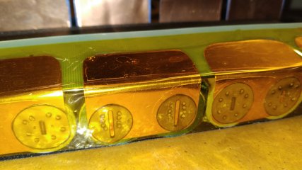
 
Except shorting dara wires and overvolting,
i tested everything on my ND721800 with my 21S Li-NMC Battery which gets charged up to 1.5V under the over voltage shut off from the fardriver.
I also tried shorting phase wires with a ND72680 when I melted them a few years ago during uphill tests 😉

I also killed two Sabvoton (a 72260 and a 72150) a few years ago, they do not like weakening field and no load conditions. The fardrivers handles this also without any problem.
 
So, how does the overvolt protection work? Is it just a big resistor or something that takes any extra voltage and turns it into heat?
 
Are you intending to weld copper with no sandwich?

I have welded 0.3mm copper under 0.2mm nickel plated steel using welding flux at about 90% of the available power of my AwithZ P20B welder.

Welding 0.2mm copper under 0.1mm stainless steel requires about 55% of its power without using flux and 38.5% using flux.

Stainless steel is the magic sandwich copper welding aid.
You will be able to weld 0.3mm copper under 0.1mm stainless with ease using the P30C, without using the special welding flux. You might be able to weld 0.3mm copper without SS sandwich or flux, but likely at near its full power.
This is a good question. I was planning on using a copper nickel sandwich, but that is only because I have seen that combination mostly (.3 copper, .1 nickel). Is the idea that the layer of nickel/steel between the copper and the cell helps fuse the two better? Is stainless steel better than nickel for the sandwich layer? Does the thickness of the nickel/steel layer matter very much or should it just be thin enough to promote fusion between copper and cell?

Thank you for the information regarding power levels and adhesion in your scenario. That helps me understand the forces required to achieve proper fusion in my own case.
 
Once upon a time i figured the nickel on top of copper would not only be a welding aid, but help carry some current too.

I realized Nickel plated steel was a much better welding aid than pure nickel
The i realized stainless steel was a much better welding aid than nickel plated steel.

Then I stopped looking at the top sandwich layer as anything other than a welding aid.

I want as thick of copper as possible touching my cells.

0.3mm copper under 0.1mm stainless steel is up nearl the limits of my P20B welder.

I only use stainless to get copper welded to the cell.

I know some want to use nickel on top of copper to increase ampacity.
I would personally much rather use thicker copper under stainless and not even have the stainless bridge the parallel or series connections.

20260212_142635.jpg


This is just a small 10s2P esk8 battery, and needs to be flexible, so the 2P series connections are dual 14awg silicone wire.

4 pairs of welds, even on the cathodem and 0.2mm copper, is likely excessive, but that is how I roll.
And I roll a lot.

Those 0.1mm slotted round stainless pieces, on top of the hand cut 0.2mm copper, were a gift from @ZEUS-FL

Shown as an example of stainless being ONLY a welding aid, which also strengthens the whole thing.
 
So, how does the overvolt protection work? Is it just a big resistor or something that takes any extra voltage and turns it into heat?
When the controller is connected to the motor and the BMS cuts out at high speed, it uses weakening field and heats the motor with the excess energy. Then the app shows undervoltage and weakening field at the same time, which confused me at first, but after the BMS had cut out a few times at cold days, I realised it was the regen current in combination with the low temperatur cut off from the BMS which protected the battery from charging and this produced the errors.
I do not know how it reacts when there is no motor connected and you feed it with to much voltage.
 
So, how does the overvolt protection work? Is it just a big resistor or something that takes any extra voltage and turns it into heat?
If you have too high voltage the controller gives an error code and wont turn on, it that is what you mean?
I could only run about 120V on my fardriver 961800, even though overvoltage was set to 121,5V.
 
Voltage readings on the Fardrivers are slightly off, mine show up to 1V more than the BMS.

j bork is running a 30S battery with the Fardriver ND981800.
28S should be no problem with the ND96 series.
 
I want as thick of copper as possible touching my cells.

0.3mm copper under 0.1mm stainless steel is up nearl the limits of my P20B welder.
So for my pack I have .3 copper chosen in my design. Does the thickness of the stainless steel even matter. Could I get away with .1 like yours?
I only use stainless to get copper welded to the cell.

I know some want to use nickel on top of copper to increase ampacity.
I would personally much rather use thicker copper under stainless and not even have the stainless bridge the parallel or series connections.
I was wondering if ampacity was going to be an issue with .3 copper. This might seem dumb, but I assumed that since the copper will be the length of my parallel groups, that it would be distributed enough to handle the amperage without heating up.
 
When the controller is connected to the motor and the BMS cuts out at high speed, it uses weakening field and heats the motor with the excess energy. Then the app shows undervoltage and weakening field at the same time, which confused me at first, but after the BMS had cut out a few times at cold days, I realised it was the regen current in combination with the low temperatur cut off from the BMS which protected the battery from charging and this produced the errors.
I do not know how it reacts when there is no motor connected and you feed it with to much voltage.
I think I follow what you are saying. Basically it dumps the excess energy back into the motor through field weakening, where it is turned into heat. While that happens it causes the BMS to cut out (specially in the cold) and throw under-voltage errors. I assume the cold was causing low temp errors as well if it didn't have the charge generating heat in the batteries?
 
If you have too high voltage the controller gives an error code and wont turn on, it that is what you mean?
I could only run about 120V on my fardriver 961800, even though overvoltage was set to 121,5V.
I was more wondering where the excess voltage went. The scenario I had in mind was:
- Running the motor hard then heading downhill and braking to spike the regen.
I assume that would mean that the controller would cut off in the event the voltage got above the over-volt protection limit?

Does the SoC matter when it comes to regen voltage spikes? Like does regen hit the system with the same voltage no matter the SoC because it's basically running the system in reverse and the power is determined by the energy in the vehicle being converted back to electricity instead of the electricity driving the motor?
 
The voltage of the regeneration depends on the battery voltage, how hard you brake and the internal resistance of the battery.
It will always be higher than the battery voltage, how much depends on how well the battery "holds up".
If it were not higher, there would be no charging of the battery. But that's the big risk with, for example, a BMS that trips, the voltage can skyrocket.
I never had a problem with it cutting out during regeneration, but that doesn't necessarily mean it can't happen of course.
 
They claim to have a 45A continuous discharge, but even being conservative and assuming I only get 35A would still net me 840A total.
Realistically its more of a 30a cell and the 45a rating is pretty optimistic, otherwise its a fine cell.
Connection: I believe .3mil copper nickel sheets would be sufficient, but I would appreciate input on this. I am also planning on using a
Calculate the cross sectional area, for ~700 800 amperes in this application 50-60mm^3 would be about the minimum off the top of my head.
kWeld to adhere the sheets to the cells. I haven't seen another welder that is able to do .3mil copper. If there is a cheaper option that won't be too frustrating, I'm open to suggestions.
I personally like the kweld, you would just need something that can dump ~1800 amps for a decent few milliseconds. Even if there are other welders that claim more power, I still prefer the kweld because of its consistency and you can actually see how much power you are pulsing and you get very fine grain control versus some obscure 'gear' or 'step' settings that many of the common chinese welders have. Though do note that you should probably upgrade both the welding and input leads to a higher gauge wire as the stock ones get very hot.
BMS: I am still somewhat confused on best practices for BMS. it seems like some people swear by active and others are passive only. I want to make sure my battery remains stable, but I don't want to waste money if there really isn't much benefit.
There isnt a right answer, it depends on what you want, the only real difference is that with a passive balancer it will take much longer to balance any large differences in cell voltage. This doesnt really matter if your cells are very well matched and balanced from the get go though...Personally I dont really bother with active as if anything actually gets to the point of needing more than a few hundred ma worth of current, somethings probably wrong with the pack and Ill be taking it apart anyways.
I was planning on using the ANT BMS 21S-30S 380 Amp with a peak of 950A. My conservative estimate parks my battery at 840A, but technically if I get the full discharge rate, the battery could hit 1080A. Is that an issue since the BMS wouldn't be dealing with discharge, so it would be charging at a designated rate under the 950A?
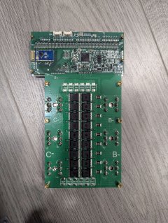
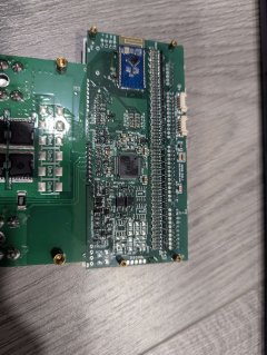
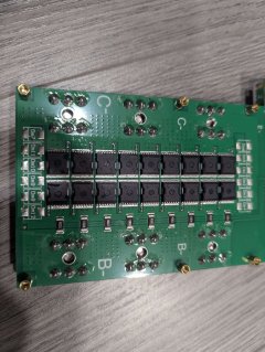
I have one of these, its pretty nice and the mosfet rating is very much in excess of the label. It has 42 of the HYG065N15NS1P/B in parallel for a total of about ~7ka but youre going to be limited by the pcb far before that. Here are some internal pics if anyones curious:
PXL_20260315_034619989.jpgPXL_20260315_034626626.jpgPXL_20260315_034629547.jpg
(may or may not have forgotten to take pics of the top side haha, but its pretty similar)https://www.lcsc.com/datasheet/C2687415.pdf
Wiring: This is really where I have no clue what to choose. From what I have seen, a pack with the amperage I am planning on would need 4/0 copper just to hit about a third of the amperage.
The awg ratings are a continuous 24/7 rating if thats what you were looking at, so a bit overkill. Generally you want to spec the output leads to be equivalent or higher to your cell connections, assuming your cell connections are ~50-60mm^3 thats about 1/0 or 2/0. Thatll go up depending on how far your inverter is from your battery though...
Charger -
What charger is recommended for 100v systems? I can find 96v all day, but it seems like thats where it stops. I know there are systems out there charging 400v, so I don't understand why I'm having difficulty finding one for my use case. Also would it be a 100A charger, or a 118A charger to account for the peak voltage?
You want the output voltage to be ~117v, if you want the cheap option, take a look at the converted telecomme rectifiers such as these, I have a couple, theyre fine for the most part though if you want to do 25 amps you will need to stick a heatsink near the rear where the 4 mosfets are as itll get very toasty very quickly. Theyre not waterproof nor are they very vibration resistant so I wouldnt permanently affix them to the cart. If you want the nicer option, elcon/tc is pretty decent, youd be looking at the
HK-MF-108-32 (or the HK-LF-108-60) though it is pretty pricey in comparison to the telecomme rectifiers. The older gen 2 (the diginow style ones) units are cheaper but theyre a lot more difficult to find though...https://www.lcsc.com/datasheet/C2687415.pdf
Controller -
Fardriver ND961000. The issue I have with this is the peak voltage is 115v.
As everyone has said already, you can set the cuttoff voltage to ~120 121v. I built a pitbike with a 96680 and a qs138 70h and ran it on two zero bricks (102v50ah) so theres no issue there.
I was originally planning on using the 1081000, but they are about 2x as expensive.
Can you actually buy these now? I know theres listings on aliexpress but theyll just cancel your order when you place said order. As far as I know they did a limited production run of these a few years ago and were having some issues with them and as a result they never made it to market...
Motor -
QS180. I went back and forth between the QS180 and the ME1616. In the end it seems like people are able to squeeze a bit more power out of the QS180. Would the QS180 really be sufficient for something as heavy as a Crosskart? I have seen a lot of people use the QS138 in ATV builds but I don't have any first hand experience with either motor to know what they feel like.
Ah the me1616.....It is the watercooled version of a me1507 which itself is a underperforming ripoff of zeros zf75-7 (which at least is actually a very solid motor). That being said, the qs180 isnt actually that much more performant, neither will be able to actually take what your battery could put out. If you actually want to make use of ~800 amps you should be looking at the offerings from emrax, parker hannafin, cascadia, engiro, and similar. Zeros zf75-10 is also a contender as well as being more affordable and easier to find, I guess you could get away with that much current on a zf75-7 (Im absolutely maxing out a gen 4.5 size 6 sevcon in my sr, so about 750 amps) but I wouldnt recommend it since it saturates right around that point... You honestly might be better off finding a wrecked gen 3 zero or an energica and transplanting the entire drivetrain. The qs138 should not even be a part of this conversation (lol).
My goal is to have something that has equal to or better acceleration than the 660cc Raptor engine I was going to use. It is rated at 36hp, not sure on torque. I don't care much about top speed. Through gear reduction, I'll cap it at like 45-50mph since the trails are all lower speed travel.https://www.lcsc.com/datasheet/C2687415.pdf
It will be a lot more powerful haha....
 
Realistically its more of a 30a cell and the 45a rating is pretty optimistic, otherwise its a fine cell.
Awesome, I figured my 35a guess was just that, but I think 30a should still fit the bill no prob.
Calculate the cross sectional area, for ~700 800 amperes in this application 50-60mm^3 would be about the minimum off the top of my head.
So I did a cross sectional analysis vertically down the length of one of my bus bars and the face has an area of 159.6mm^2. I don't totally understand how that fits into the example calculation above. If it were ^3 wouldn't that just be the volume of the whole bus bar?
I personally like the kweld, you would just need something that can dump ~1800 amps for a decent few milliseconds. Even if there are other welders that claim more power, I still prefer the kweld because of its consistency and you can actually see how much power you are pulsing and you get very fine grain control versus some obscure 'gear' or 'step' settings that many of the common chinese welders have. Though do note that you should probably upgrade both the welding and input leads to a higher gauge wire as the stock ones get very hot.
I didn't even know about the 'gear' or 'step' settings. Surprising, I know... Good to know about the fine control and updating the leads tho. I have a feeling I'd be heating the leads up pretty fast doing 600+ cells.
There isnt a right answer, it depends on what you want, the only real difference is that with a passive balancer it will take much longer to balance any large differences in cell voltage. This doesnt really matter if your cells are very well matched and balanced from the get go though...Personally I dont really bother with active as if anything actually gets to the point of needing more than a few hundred ma worth of current, somethings probably wrong with the pack and Ill be taking it apart anyways.
I plan on measuring all the cells and pre-balancing them before assembling everything, along with grouping the most similar cells to keep everything as balanced as possible.
I have one of these, its pretty nice and the mosfet rating is very much in excess of the label. It has 42 of the HYG065N15NS1P/B in parallel for a total of about ~7ka but youre going to be limited by the pcb far before that.
What do you mean that I would be limited by the pcb?
The awg ratings are a continuous 24/7 rating if thats what you were looking at, so a bit overkill. Generally you want to spec the output leads to be equivalent or higher to your cell connections, assuming your cell connections are ~50-60mm^3 thats about 1/0 or 2/0. Thatll go up depending on how far your inverter is from your battery though...
I figured it was overkill, but def don't know enough about it to make that call. Is there any issue running larger cables 1/0 or 2/0 as far as physical connections go. Like is there a limit on the controller or the BMS that the terminals have to be under a certain size?
You want the output voltage to be ~117v, if you want the cheap option, take a look at the converted telecomme rectifiers such as these, I have a couple, theyre fine for the most part though if you want to do 25 amps you will need to stick a heatsink near the rear where the 4 mosfets are as itll get very toasty very quickly. Theyre not waterproof nor are they very vibration resistant so I wouldnt permanently affix them to the cart. If you want the nicer option, elcon/tc is pretty decent, youd be looking at the
HK-MF-108-32 (or the HK-LF-108-60) though it is pretty pricey in comparison to the telecomme rectifiers. The older gen 2 (the diginow style ones) units are cheaper but theyre a lot more difficult to find though...Datasheet - LCSC Electronics
I was thinking it would be convenient to have the charger onboard, but since it's going to have a pretty rough life, I'll probably keep it independent. That being said I will still look at that nicer charger and see if it will fit the bill. Thanks for the recommendations.
Ah the me1616.....It is the watercooled version of a me1507 which itself is a underperforming ripoff of zeros zf75-7 (which at least is actually a very solid motor). That being said, the qs180 isnt actually that much more performant, neither will be able to actually take what your battery could put out. If you actually want to make use of ~800 amps you should be looking at the offerings from emrax, parker hannafin, cascadia, engiro, and similar. Zeros zf75-10 is also a contender as well as being more affordable and easier to find, I guess you could get away with that much current on a zf75-7 (Im absolutely maxing out a gen 4.5 size 6 sevcon in my sr, so about 750 amps) but I wouldnt recommend it since it saturates right around that point... You honestly might be better off finding a wrecked gen 3 zero or an energica and transplanting the entire drivetrain. The qs138 should not even be a part of this conversation (lol).
I don't know that I actually want to take advantage of the full power of my battery. I was building it with range in mind more than torque. I would still like to have a peppy machine, but as it's my first attempt, I also want to keep it reasonable and semi easy to implement. I appreciate the recommendations and I will be looking into them as well, but it does appear that the QS motors have a bit more users (from what I have found), making them easier to get help with when I have a problem. I will say transplanting a drivetrain might be the simplest, but I have concerns about getting locked into an ecosystem. Oh and the QS138 was never an option, I had just seen it a lot in ATV builds to get an idea of the power they could output as a baseline : ).

All that being said, where do most people get their motors from? I have seen ali express a lot and that sketches me out. Ebay also has a few postings and I'm not as sketched out there, but if there is a reputable seller I would rather go there.
It will be a lot more powerful haha....
Now I'm getting my hopes up!
 
So I did a cross sectional analysis vertically down the length of one of my bus bars and the face has an area of 159.6mm^2. I don't totally understand how that fits into the example calculation above. If it were ^3 wouldn't that just be the volume of the whole bus bar?
I completely misspoke haha, meant mm^2 which would be the cross sectional area rather than the volume. Apologies.
I didn't even know about the 'gear' or 'step' settings. Surprising, I know... Good to know about the fine control and updating the leads tho. I have a feeling I'd be heating the leads up pretty fast doing 600+ cells.
Yeah, kweld lets you set a particular joule amount and then alters the pulse time to get that power output. Its actually pretty neat.
I plan on measuring all the cells and pre-balancing them before assembling everything, along with grouping the most similar cells to keep everything as balanced as possible.
Youd be fine with either then! Its up to you if you want to go with active or not.
What do you mean that I would be limited by the pcb?
The pcb is not able to carry that much current, just guesstimating based off thickness and potential fill I wouldnt really go over 2ka (I dont even remember if the software lets you set it that high...I dont believe so, bit of an irrelevant point haha...)
I figured it was overkill, but def don't know enough about it to make that call. Is there any issue running larger cables 1/0 or 2/0 as far as physical connections go.
Nope (apart from it being a little harder to work with, heavier and a bit more expensive), you just get less resistive losses.
Like is there a limit on the controller or the BMS that the terminals have to be under a certain size?
Depends on exactly which inverter and bms you get, you would need to spec the lugs according to that.
I was building it with range in mind more than torque.
Range is determined more on your riding (driving?) style and battery capacity rather than the theoretical power output of the system.
but it does appear that the QS motors have a bit more users (from what I have found), making them easier to get help with when I have a problem.
I mean, at the end of the day motors are just three phases and some hall sensors (or an encoder) so I dont see that much risk in using something that isnt as common, but its still a valid concern to have.
I will say transplanting a drivetrain might be the simplest, but I have concerns about getting locked into an ecosystem.
That is a fair concern, I am maybe a bit biased in that regard as I enjoy mucking about with zeros hardware haha.
All that being said, where do most people get their motors from? I have seen ali express a lot and that sketches me out. Ebay also has a few postings and I'm not as sketched out there, but if there is a reputable seller I would rather go there.
It depends on what youre buying, aliexpress is fine for basically everything apart from batteries/cells. Never buy these from ali/ebay/amazon/whatever else, always buy from a trusted supplier. Anyways, always check the ratings and the age of the store on aliexpress youre buying from, generally you want someone who has a decent number of positive ratings and has been around for at least a few years. If youre buying qs stuff you can also email them directly, the only real site is QS MOTOR Official Web Electric Motor Leading Manufacturer.
 
Range is determined more on your riding (driving?) style and battery capacity rather than the theoretical power output of the system.
Yeah how I drive is a big factor, but I was thinking that my capacity was the ah of the battery? I confuse the output with the capacity a lot. So 4200mAh cells times the number in parallel (24) gets me the capacity of the pack (~100ah)? The power of the system would be considered the max discharge (~30a) times the number in parallel (24) to get me 840amp. So if my driving uses lets say 50amp/hour average, then I would get 2 hours of drive time (ignoring regen)? I guess I don't understand how I could increase range without increasing voltage or amperage. I would need more cells since the ceiling is pretty low on how much mAh they can pack into each cell.
 
I don't have much to add, sorry... except maybe, buy once > cry once. Super interested in seeing this come together though 🤓
 
I don't have much to add, sorry... except maybe, buy once > cry once. Super interested in seeing this come together though 🤓
Always good advice. I can't wait to get started. Steel should be coming in soon, but this is going to be a back burner project unfortunately. There always seems to be other things that need time. That being said I will update this post as I make progress!
 
Back
Top