2001 Polaris Sportsman Conversion

majerus1223

10 mW
Joined
May 20, 2025
Messages
31
Location
na
Starting on my first conversion. I am looking to exceed stock power and generally make the machine feel alive.

I have been kicking around the idea of a qs180 90h , with a nd961800. However after looking around the site now I am not sure. I also received a quote for a me1616 with a sevcon controller. The price is quite high, along with the forum posts about low power have me concerned.

Is the qs and the Me1616 in the same power level functionally? The qs is rated way lower, however I see in multiple places folks talking about 50kW with these things, and others talking about the ME1616 only able to hit 36kW with anything below 100V.

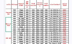
The battery I am thinking about would be comprised of 2 of the alfa cells below, wired in series. Would this work, or am I missing something? I assumed I would need to use something like an ANT BMS 400A bms as the factory one would need replaced .


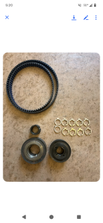
Already have the bike torn down, now just trying to buy all the parts and get to building. Thanks for the help!


1747798266804.png
1747798296129.png
 
sevcon is expensive and hard to program.... you'll be tied to the dealer. Don't recommend it. Buy anything else and program it :)
Those batteries? you'll need to replace the BMS of course and also consider that they are aged.

Don't know much about converting these kinds of vehicles. Hope you get some help here and good luck!
 
Alright just pulled the trigger on the following

QS180 90H - Bought from Alan from QSMOTOR


The following from econiccycles
ND961800b, throttle, and a chaojie 6.86 display.

Need to figure out the battery now
 
Reached out to amorge to see what type of battery they can put together.

Was also able to source some parts for the pulley drive from a nice guy off Facebook. Making progress, hopefully have all the parts besides the battery in next week or so.
 

Attachments

  • Screenshot_20250529-172004.png
    Screenshot_20250529-172004.png
    5 MB · Views: 6
Built mock batteries today, jeep / alfa / q5 sizes.

Wanted to put the batteries on the top frame rail, however looking at things now I will be forced to where the engine was. 1748831941454.png1748831932679.png1748831926652.png
 
Last edited:
Controller and display made it here as well. The controller weights a lot more than I figured it would.


1748832251899.png1748832081383.png1748832062763.png
 
Here is what Amorge sent me for dimensions and pricing on 96v options. Also what the total price was after shipping etc. They technically have a US based office so tariffs should not be a surprise issue. I did get hit with added fees for my motor and controller from SiA. Another $400 at the boarder that DHL charged me. The battery was to my door for the price on the receipt.
 

Attachments

  • Screenshot_20250203_214451_Gmail.jpg
    Screenshot_20250203_214451_Gmail.jpg
    336.7 KB · Views: 11
  • Screenshot_20250401_141401_Gallery.jpg
    Screenshot_20250401_141401_Gallery.jpg
    136.3 KB · Views: 12
After waiting forever to pick batteries went kia ev6 modules from Greentechauto last night. As well as a JK BMS B2A24s30P-HC . Have a couple messages out to alibaba for a onboard charger with j1772 ability. From there should have all the parts which can keep the project from stalling anymore.

1765394154029.png1765394163623.png

1765394245204.png
 
Checked all the cell voltages I think they seem fine. However Greentec didnt ship the cell taps so going to have to wait to balance the pack. As of right now 2 of the modules are at 24.09V, and the other 2 are 21.73. I am going to drain the 2 higher modules to match the voltage of the lower modules than parallel them until I can build the pack completely.

1767111779913.png

The charger has also just shipped so I am waiting for that, and the J1772 plug . The charger I went with is a 3.3kW from Longrun. To bad the price on the site isnt really what the price is after all the import fees :( .

1767111860589.png


I have been also working on the motor mount mocking it up in freecad, and trying to learn that. Compared to fusion I think its working pretty well. Ill have send cut send cut out the mount once I am happy with the design.


My test print turned out to be the wrong size, thankfully I printed it before having SCS work on the part.

1767111997025.png

Finished print..

1767112030862.png

Whoa what just happened :)

1767112056820.png

I have also got the display and ignition mounted and created .
1767112117021.png1767112128997.png1767112151075.png1767112169035.png1767112191743.png


I was also able to find a pully for the transmission from a local shop . Happy with the result, the motor side pully is at a machine shop to fit the Qs motor. 1767112430033.png
 
Little bit of a weekend update.. Still waiting for the machine shop to return my pully that will mount on the motor side.

I worked with a guy on Upwork who was really helpful in getting a part redesigned for the motor bracket, which should help. Plan to get this sent to sendcutsend this week and get the motor in next weekend.


Motor controller has been mounted
1767577490207.png

Was able to run a test on the display with a power adapter. Reached out to the manufacture to see if could update the image of the scooter. Apparently its not possible which sucks. Once the project is running ill hack around on the display and see if i can get into it . Otherwise maybe replace it with something else.

1767577538944.png


Battery balancing is a work in progress found a 24v motor and using it to drain the 2 higher state of charge modules down. Will need some more time but way faster than the RC charger I was using.

1767577670399.png
1767577698491.png


Bit of a side project took shape as well. Converted a laser cutter into a bit of a plasma table. Using a 5v relay. Also ran into compressor problems which delayed things a bit but everything is sorted now.

1767577880974.png
1767577906078.png
1767577851582.png1767577836642.png1767577796366.png
 
Today was able to get the harness made for the cell taps, and the batteries wired to the Battery Management System (BMS) on the workbench. Turned it on and as of right now the bms is working on the balancing. Also got word my buddy was able to whip up a new idea for a motor bracket so things are progressing.


Cell Harness Build

1768803910862.png


1768803953531.png

1768803969346.png


1768803986065.png


Finished harness, Each module has 2 cell taps that are connected to it.

1768804019959.png


While I was testing blew out a fuse on the BMS board. By passed it as I do not have any of these fuses on hand. Was pretty sketchy taking the front cover off.

1768803811597.png
1768803865493.png
If i keep blowing fused ill design a replacement pcb.
1768803828581.png
1768803733725.pngBypassed fuse.
1768803680110.png


BMS Wired up with the cell taps.

1768803504994.png

1768803561761.png


JKBMS Screenshot Balancing
I turned off discharge side for the night.
1768804083899.png1768804116839.png

Motor Mount Plate..


The motor mount that was cut out with the CNC Plasma will sit on this. Should provide better placement and adjustability for the motor.

1768804200123.png1768804216079.png1768804207744.png
 

Attachments

  • 1768803540976.png
    1768803540976.png
    3.1 MB · Views: 0
  • 1768803637356.png
    1768803637356.png
    2.8 MB · Views: 1
I happened when I was probing around , noticed the spark as well. The BMS looks like 2 amps. For the fuse I did some searching, but there are no real markings on it to determine its size from what I can see.

1000057007.png
 
Balancing seems to be done. Disconnected the pack, and put the modules together. Any concern with this orientation with the cells I am using?

1768883839665.png


1768883856282.png


1768883868078.png


Washers had to grind down to fit..
1768883978297.png
1768884000016.png

Last screen shot of BMS before removed it to put the pack together.
1768883938814.png


Figured I would try to run this pack without cooling and monitor it. If it needs it with the workload of the project ill add a cooling plate in the middle between all the modules.
 
Looks like a great build. Any update on your progress? I have done a couple of conversions on small kids quads but they were a little under powered. I am curious how your build is going as I am hoping to try a larger conversion as well.
 
Its progressing we had a pretty huge storm here so been a bit slow. The battery box is a thing I am trying to figure out as things stand.
 
Have things to the point where the motor is ready to be mounted, however held up on mounting the pully to the motor. The QS180 comes with a shaft that is cut for a sprocket to be mounted. My initial plan, and given how this is progressing might need to change course. Was to just cut threads for a bolt to secure the pully to the motor. Drilling a hole in the shaft of this motor is turning out to be an issue. I assume its hardened steel at this point.

I am going to pick up a carbide drill bit and see if I am able to drill any further. If not figure these are my next two options.

One have the face of the pully machine down a bit, so the keeper for the sprocket can keep the pully. As it stands now the face is a bit to proud for that to work. Then have two holes machined and tapped to bolt the keeper.

Second option take the motor to a machine shop, and see if they can drill a hole and cut threads into it.

Motor Mount Plate


1769999732079.png
1769999783009.png


Pully alignment

1769999807516.png 1769999826269.png


1769999896655.png

Motor drilling operation issues.

1769999930671.png
1769999977006.png


Keeper idea.. 1769999954263.png
 
Dropped the motor and pully off at the machine shop after wrecking more drill bits. Going to try to drill and tap the shaft if that looks like it wont work. The pully will be ground down, and the keeper will be have holes drilled and tapped into the pully. Might be two weeks before I get the motor back however. In the mean time on to wiring I suppose.
 
Disconnected the pack, and put the modules together
I really like those Kia 6S modules. It's really nice to have access to M4 cell terminal screw and BMS board.
Do you put some insulator or foam between unprotected cells under the module?
 
I am thinking about maybe adding a cooling plate so nothing between the cells yet. The plastic on the endcaps are the only parts that are touching between the modules.
 
Back
Top