Transmagnetics 5 / 5.25 inch 3kW motor info +reduction ideas

neptronix

Administrator
Staff member
Joined
Jun 15, 2010
Messages
19,615
Location
Utah, USA
Been meaning to post this for a while, so here's a pic dump with commentary..

More info on the motor here, but to summarize quickly, it's rated for 3kw on 48v, peaks at about 92% efficiency, and has roughly a 70kv.

http://www.endless-sphere.com/forums/viewtopic.php?f=31&t=44058

transmag_03.jpg


15mm shaft..

transmag_04.jpg


Keyway is the usual 3/16ths.

transmag_05.jpg


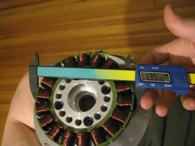
outer diameter is 138mm.

transmag_06.jpg


10AWG phase wires - awesome!

transmag_07.jpg


I believe this is 127mm the other way..

transmag_08.jpg


inner shaft is about 17mm.

transmag_09.jpg


A look inside after popping the back case off.
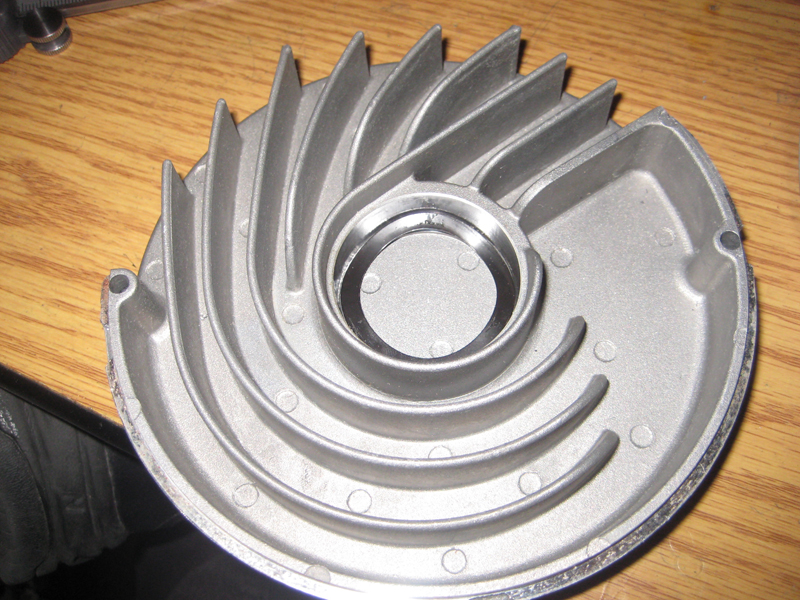
transmag_10.jpg


Nice intake design :)

transmag_11.jpg


The magnet assembly is an interesting design. Laminations should be 0.5mm.

transmag_12.jpg


magnet assy. is 33.5mm thick.

transmag_13.jpg


and 75.5mm wide

transmag_14.jpg


One magnet is a bit out of place..

transmag_15.jpg


Here's the interior look at the stator. The windings are very tight and precise all around.

transmag_16.jpg


Another look.

transmag_17.jpg


33.19mm thick.

transmag_18.jpg


Total diameter of stator would be 116mm.
Edit: 'roller' says it is 133.35mm (5.25"); i suppose this includes the iron? ring around the stator.

transmag_20.jpg


Lam count and view.

transmag_21.jpg


Lower cover is almost 1lb.

transmag_22.jpg


Magnet assy + fan + shaft = almost 3lb.

transmag_23.jpg


Top cover is almost 1lb.

transmag_24.jpg


stator + outer case is a little over 6lb.

transmag_25.jpg


entire motor comes in at almost 11lbs, but not quite.

I thought the motor was going to be larger, but it's more like an overgrown RC motor with halls, a low pole count ( any controller that can push a MAC / BMC hub motor, which has 16 poles, should have no problem pushing this motor, which has less. ), and a very robust looking cooling solution.

Edit: thought i'd add this in here.. might be important... :)

Hall / phase wire info from drewjet is as follows:

Phases:
A - Black
B - Green
C - Yellow

Halls:
grd - black
+5v - red
a - green
b - yellow
c - brown
temp - blu

I will test this tomorrow to ensure that it is proper.
 
thanks for the review! great pictures and interesting details.

The Zero 2013 motor is similar inrunner desing as this one but i a larger diameter and more pole count

I see that the winding coil are protected by what look like black plastic ?.. if so that would limit the power rating i guess. our great hub motor dont have plastic anc can take 180 celsius burst without problem.

What is the max rpm of that motor? and is it limited by the bearing or the magnet holder or inductance?

Doc
 
'Roller' says that the stator losses end up matching copper losses around 6,000rpm. I think he said that the bearings have a lower lifespan at that point. I'm estimating that it would take 96v to hit that RPM under load, so 72v should produce about 5,000 RPM unloaded.. so that's prolly a good way to play it safe.

3.8 kW continuous output on 72v ( 4.5kw in? ) seems to be the most this motor can tolerate on 72v. Surely you can push dramatically more power for short periods of time. But you probably know by now that smaller motors have a lower thermal mass and can't be abused as long as hubs can.

You can see more details on the thread at the top of the first post. I am just repeating what i've read here..

I will get a more exact kV when i manage to spin this motor up. But i need a 5 pin chinese hall sensor connector that comes standard on the infineons. Any idea where i can buy one of those?
 
I found some parts that may mean a boon in experimentation with this motor.

Here is a recipe for a single reduction 5:1 system, which will give you about 560rpm at the wheel, from an estimated 2800 RPM loaded figure on 48v with this motor. You can go with lower ratios if you want higher speed on 48v, but 5:1 is recommended if you have hills, headwinds, are upright, etc.

560RPM is approximately 43mph on a 26" wheel, 40mph on a 24" wheel, 33mph on a 20" wheel.

wheelspeed 26":
380rpm at 30mph
450rpm at 35mph
512rpm at 40mph

wheelspeed 24":
410rpm at 30mph
485rpm at 35mph
560rpm at 40mph

wheelspeed 20":
500rpm at 30mph
590rpm at 35mph
670rpm at 40mph

Keep in mind that this motor is rated for 3kW continuous on 48v. This means that if it maintains upper 80% efficiency figures, on an upright bike, it could probably do 42-43mph continuous. Thus, I strongly recommend gearing for close to 40mph top speed, as 40mph continuous means for approx. 2000-2500w continuous. A headwind or hill will increase that wattage figure.

So without further ado, here are the parts i have found for a !5:1 reduction.

http://www.staton-inc.com/store/pro...heel_Sprockets_1_wide_2_set_screws-874-0.html

15mm inner diameter english thread sprocket adapter.. having the same threading that comes on bike freewheels, track cogs, etc.

http://www.tracksupermarket.com/index.php?main_page=product_info&products_id=224
http://www.niagaracycle.com/categories/all-city-12t-x-1-8-track-cog-black

12T 1/8" chain ( BMX chain ) track cogs.

http://www.longleafbicycles.com/products/fixed-gear-and-singlespeed/track-cogs-lockrings/

Here are some 13Ts. Run it to a 60T chainring out back, you will only get a ~4.6:1 reduction ratio to 60T. This would be fine if you are running 20" wheels, but not recommended for larger wheels.

For the chainring adapter.. this is expensive, but worth every penny. I've wasted hundred of dollars on other solutions, and they suck. This would gives you the inwards offset that you need for running on a standard frame with tapered chainstays. These are typically used with high powered ( 10,000w? ) astro drives, so they should hold the power this motor puts out just fine.

http://www.outriderusa.com/Chainring-Adapter-130mm-BCD-p/11chainringadapter.htm

And for some chainrings..

http://www.vueltausa.com/components/chainrings/se-flat-chainrings/se-chain-ring-130mm-38-60t-1.html
http://www.wiggle.com/ta-130-pcd-alize-outer-chainrings-57-61t/

60T - 61T 130BCD aluminum chainrings. Unfortunately these are mostly 3/32 ( 6-8 speed chain ), but since we are talking about such a friggin' tall gear out back, it may hold - i am not sure.
The 'TA' ones are made out of 7075 aluminum, which is very strong.

1/8 is best, and these are various places where you could pick up a 1/8 ( BMX / single speed chain width ) sprocket, or have one custom made for your application.

http://www.homebrewedcomponents.com/store.php
http://www.candycranks.com/chainrings
http://www.warhawkindustries.com/custom-chainrings.html
http://fyxo1.mybigcommerce.com/d1-chainring-130-144-bcd/ ( 1/8" and up to 56t!! )
http://fyxo1.mybigcommerce.com/custom-chainring/ ( custom sizes, maybe they could be convinced to do ~60T! )

Now go play with this motor, peoples :)
 
But i need a 5 pin chinese hall sensor connector that comes standard on the infineons. Any idea where i can buy one of those?

I don't know which connector you need, but these guys have a bunch of the standard ones by the piece.

http://www.electricscooterparts.com/wireconnectors.html
 
I just had another idea.

http://www.staton-inc.com/store/pro...h_1_2_ID_1_8_key_way_2_set_screws-709-50.html

Here is a 10T 1/2in diameter #410 ( 1/8" ) sprocket.

1/2 an inch is 12.7mm.
It would probably be no problem for statton-inc to bore this out to 15mm. There is a little extra meat here. They do that kind of machining anyway.

http://www.staton-inc.com/store/pro...Plated_Zinc_Plated_two_set_screws-693-50.html

Here is an 11t #410 ( 1/8" ) sprocket. 5/8 internally - but maybe he is machining this from a smaller diameter?

These would be definitely stronger than

I am have sent an email to statton-inc and see what they can do. This would be better than the freewheel adapter idea, just based on the strength of the sprocket alone.
 
Rassy said:
But i need a 5 pin chinese hall sensor connector that comes standard on the infineons. Any idea where i can buy one of those?

I don't know which connector you need, but these guys have a bunch of the standard ones by the piece.

http://www.electricscooterparts.com/wireconnectors.html

Thanks for the link. I actually shot lyen an email and picked up 3 from him already though. That's cool that they have both sides for sale on that site. :)
 
nep - -- I could probably get you a seat on a Chinese assembly line, if you wanted . . . you can dis/assemble all the motors you want!
--- go easy putting that rotor back in stator -- it's got some finger pinching pull. We do it with a fixture so mags can't hit the steel.
-- stator OD = 133.35mm (5.25")

drBass - nylon 6/6 for the core insulation: melts around 280C, stays stiff/strong enough up to the 180C of the coil insulation.

without condoning it -- I've run this diameter structure at 13k r/m for a fan application. That takes rotor balancing and core heat dissipation. I don't know the limits for vehicle application, but Neptronix is probably right about 72V as a safe max operating voltage.

that said -- I (or competent E-Ser) can re-wire these for lower Kv (higher Kt) by a factor of 2 or 4. I forgot about that in the sale thread, will have to follow up.

-=rlr=-
 
Thanks for the input, roller.
~70kv is actually really perfect for this kinda application, but the ability to rewind is totally cool.
I will figure out the hall/phase wiring tomorrow and spin it up, video incoming.
 
SpinningMag - "Y" connected

Nep - if your controller uses a "normal" logic, here's a correlation:

phase :::::: Halls
Black -- A -- green
Green -- B -- yellow
Yellow -- C -- brown

::::::::: +5 -- red
::::::::: grnd - black
::::::::: temp -- blue
 
Thanks!
I used your wiring formula and she spun up correctly the first time.

[youtube]3-jbkL75-l0[/youtube]

No load stats:
38.2v 105w 2800rpm
57.5v 210w 4164rpm
76v 370w 5500 rpm

Looks like 73kV.
The controller wouldn't kick into 120% mode, so i think that the EB3 controller is starting to get taxed at 5,500rpm. If we translate that into 85% of the no load to get the loaded speed, then we're looking at 4675RPM on 20S/76v. I'm pretty confident that a garden variety EB3 infineon controller can handle this RPM.

Compared to the MAC 2kW motor, it's nearest competitor:

38v: 2688RPM / 3.15A x 38v = 119.7W loss
57v: 3878RPM / 3.6A X 57v = 205.2W loss
78v: 5037RPM / 4.0A x 78v = 312.0W loss

Not too bad considering that the MAC motor doesn't have a fan on it, and is capable of much less power. That fan moves a lot of air at that speed. I really wonder how much power the fan is taking up. But i am not curious enough to chip off the epoxy/glue that holds the fan on and find a suitable replacement, hehe..
 
cool, Neptronix. Just make sure your brakes are up to snuff on your bike!

This motor structure (in a sealed package on the Jackalope) had me going about 45mph with 4.4:1 GR on 20" wheel.


Thread note: This is the Transmagnetic 532 ( "5" inch {really 5-1/4" stack OD}, 32mm stack length) motor, not the 4" , (implied in the title).
 
Facepalm... sorry bout that, title corrected and updated for better search ability.

As for brakes, i have a 203mm rotor up front and will be setting up the motor to do regen. I won't be doing >40mph often at all. Maybe just once and a while to blast the blues off my face ;)

I should be testing this fairly soon. I'm anxious to run it.
 
Just FYI...
I managed to convince staton-inc to makes some 15mm inner bore #410 ( BMX/single speed ) sprockets.

http://www.staton-inc.com/store/cat..._Roller_Chain_1_2_Pitch_x_1_8_Width-50-1.html

He should have a few more in stock.

Just keep in mind that #410 is probably not the strongest or longest lasting chain/sprocket type for this application. But these will get you up and running if you are going to use a FFRTrikes/outrider adapter with a large #410 chainring.
I'm going to set mine up this way though, despite the fact that it's a bit weak.

I think perhaps later on, some #35 would be warranted for this kind of use, if i can get proper sprockets cut out for the job anyway.
 
neptronix said:
That fan moves a lot of air at that speed. I really wonder how much power the fan is taking up. But i am not curious enough to chip off the epoxy/glue that holds the fan on and find a suitable replacement, hehe..
I asked myself the same question, what is the difference between vented and enclosed version?
I know, vented has vent... :mrgreen: But shouldn't that vent effect efficiency, or at least max power,
or something? I looked at the numbers on Transmagnetics web, and all the numbers match (torque, current, rpm and so on for vented and enclosed version).
 
Well, it sure can shed a lot more heat, at the cost of a little extra power used to move the fan.
Maybe roller has more to say.
 
The cooler the motor runs, the less resistance the copper has, so the small additional drag of this well-understood fan type might break even on its benefit/drawback ratio.
 
rodney said:
neptronix said:
That fan moves a lot of air at that speed. I really wonder how much power the fan is taking up. But i am not curious enough to chip off the epoxy/glue that holds the fan on and find a suitable replacement, hehe..
I asked myself the same question, what is the difference between vented and enclosed version? I looked at the numbers on Transmagnetics web, and all the numbers match (torque, current, rpm and so on for vented and enclosed version).

Personally - I wouldn't even consider the fan "consumption" compared to what it provides:

Peak power is a function of the motor structure ( copper/steel/mags, {controller, yadda, yadda}), but Continuous power (as % of that peak) is a function of the package (vented vs. sealed, inrunner vs outrunner etc). All else being equal, the vented structure will have 100% !! higher continuous output than the sealed (ignoring rpm, potting, oil-cooling, etc). This motor (in customer application) has a continuous 1.5kW input when enclosed, and continous 3kW input vented.

I think you can give up a few watts (maybe 10-20?) for the fan, to double the continuous power.
 
Thanks for this thread. That's a neat rotor.
 
I just bought one of these to build my first mid-drive setup. I have been brainstorming my approach to mounting and gear reduction and was hoping to get some feedback from you more experienced motor folks.

Anybody see a reason why a clamp style mount in the center of the can would be a problem? I am a little freaked out by the fact that there are only those 2 bolts sandwiching the ends together. Seems like it would want to spin the can on the end plates.

I was thinking of shortening the shaft and machining new endplates to help keep the overall motor length down for pedal clearance. Do you guys think the spiral intake slots cast into the endplate are really a benefit over an endplate that just has holes in it?

Any reason the rotation of this motor couldn't be reversed by switching halls/phases?
 
Howdy Dan ~

you can clamp the can - but you should also catch a notch in the face, to resolve torque. the clamp may allow the housing to spin . . . Also -- unless clamp is wide, some flex may allow the shaft to be not parallel to the axis of your wheel.

endcaps are held 90% by friction (press fit), 10% by screws. Screws largely serve to hold things together during thermal expansion/contraction, as well as resolve torque so the stator can't spin inside the housing (though, friction does 90+% of that as well).

should you shorten the back end - keep in mind you'll be re-locating the rear bearing inward; that will take some shaft mod as well. The spiral vents (+ baffle, not included) are utilized when a controller is mounted to the back of the motor. For external controller, you're fine (maybe even better) with holes in the back face (or housing perimeter).

reversing is your controller's job.

-=r
(from lovely Hangzhou, Zhejiang, China)
 
Back
Top