stinger012
10 µW
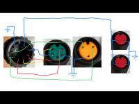
(edit: i may have solved it)
i recently purchased the old v1 motor controller for my tsdz2b motor, with the hopes of swapping the controllers to allow me to run the osf. however ive had a problem with wiring, as the connector for the display and throttle/brakes is not the same between the two controllers.
my plan was to simply cut and swap the connectors, but it looks like the v1 and v2 controllers have some dissimilar coloured wires, so it might not be as straightforward as connecting blue to blue, red to red etc.
just wondering if anyone has any advice or if anyone knows the pinout of the v2 controller? any help would be super appreciated, thanks!
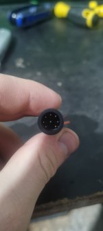
 v1 controller connector
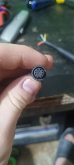
 v2 controller connector

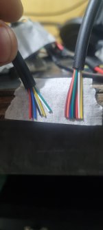
v1 controller (right)
v2 controller (left)
looks like the v2 controller has a grey and purple wire, while the v1 has brown and orange. all others are the same
i recently purchased the old v1 motor controller for my tsdz2b motor, with the hopes of swapping the controllers to allow me to run the osf. however ive had a problem with wiring, as the connector for the display and throttle/brakes is not the same between the two controllers.
my plan was to simply cut and swap the connectors, but it looks like the v1 and v2 controllers have some dissimilar coloured wires, so it might not be as straightforward as connecting blue to blue, red to red etc.
just wondering if anyone has any advice or if anyone knows the pinout of the v2 controller? any help would be super appreciated, thanks!
 v1 controller connector
 v2 controller connector
v1 controller (right)
v2 controller (left)
looks like the v2 controller has a grey and purple wire, while the v1 has brown and orange. all others are the same
Last edited:


