GGoodrum
1 MW
fechter said:It does make a nice way to automatically disconnect a bulk charger once the current gets down to 120ma...
Okay, now you have my attention...

How would this work?
fechter said:It does make a nice way to automatically disconnect a bulk charger once the current gets down to 120ma...
the optos you mention have a fairly low CTR (current transfer ratio). the ones i specified i chose specifically because they have a 500% CTR so that a milliamp into the led can cause the output transistor to sink the necessary 5 ma.rf said:On that LVC circuit. Was poking about mouser and found a few quad optos that might be preferrable to the cny17.
http://www.avagotech.com/search/results.jsp?src=&siteCriteria=ACPL847
Richard
I thought they were actually slightly better. Perhaps I misread. Thought they were meant to be the same part only quad.bobmcree said:the optos you mention have a fairly low CTR (current transfer ratio). the ones i specified i chose specifically because they have a 500% CTR so that a milliamp into the led can cause the output transistor to sink the necessary 5 ma.rf said:On that LVC circuit. Was poking about mouser and found a few quad optos that might be preferrable to the cny17.
http://www.avagotech.com/search/results.jsp?src=&siteCriteria=ACPL847
Richard
if you could find a multi-channel opto with a 500% CTR it would probably be fine.
GGoodrum said:fechter said:It does make a nice way to automatically disconnect a bulk charger once the current gets down to 120ma...
Okay, now you have my attention...
How would this work?
rf said:I thought they were actually slightly better. Perhaps I misread. Thought they were meant to be the same part only quad.bobmcree said:the optos you mention have a fairly low CTR (current transfer ratio). the ones i specified i chose specifically because they have a 500% CTR so that a milliamp into the led can cause the output transistor to sink the necessary 5 ma.rf said:On that LVC circuit. Was poking about mouser and found a few quad optos that might be preferrable to the cny17.
http://www.avagotech.com/search/results.jsp?src=&siteCriteria=ACPL847
Richard
if you could find a multi-channel opto with a 500% CTR it would probably be fine.
Richard
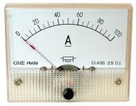
shinyballs said:Bought these stuff from allelectronics. How do I wire shunt to Amp meter? For the volt meter, does it have to be inline? thx...
fechter said:....The capacitors just need to be rated for a higher voltage than you're going to run, and as much capacitance as you can physically fit in the space. More is better. The physical size of the caps will be the determining factor.......
shinyballs said:thank you bob, fecht! yea shunt is really huge. is it ok if I use 22g wire for both meters? power source I'm using is 72v 14A
)RLT said:Reverse calculating the 'factory' voltage drop of around 30V and the 1200 ohm resistor that is in there I come up with .025A Could that be right? If so, I should need 4400 ohms at 3 watts. ... Or am I totally wrong???
RLT said:I'll post photos of the modification if anyone wants..
fechter said:OK, now you can directly drive one of those surplus treadmill motors.
The real test will be when you draw enough current to hit the limit.


fechter said:If you look around, you might find a 5w resistor that has an aluminum body. These kind can be bolted to the heatsink so you could mount it inside the box too.
fechter said:If you keep the outside caps, be sure to glue them to the case with silicone or hot melt glue to prevent the leads from bending and breaking off.
fechter said:Now for some 120v batteries! Danger! Three DeWalt packs in series?