I am looking for BMS to control 24v LiFePO4 pack. And found interesting DIY open source solution:
https://github.com/simat/BatteryMonitor.git
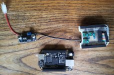
The author uses beaglebone with added simple battery interface comprising a resistor divider network and a few multichannel 16 bit A/D chips to convert the battery cell voltages to a digital signal which gives a resolution of around 1mV for a 24 volt battery
It's totally new to me, but i've checked the manual and it seems pretty doable.
Since it's pretty much a linux computer, you can access all the data online if it's connected to the WIFI.
Very useful feature if you are away.
What are the cons of 'beaglebone/raspberry pi 2/arduino/etc' approach comparing to regualar BMS systems?
Attaching couple images + getting started from github so you can see what i am talking about.
https://github.com/simat/BatteryMonitor.git
The author uses beaglebone with added simple battery interface comprising a resistor divider network and a few multichannel 16 bit A/D chips to convert the battery cell voltages to a digital signal which gives a resolution of around 1mV for a 24 volt battery
It's totally new to me, but i've checked the manual and it seems pretty doable.
Since it's pretty much a linux computer, you can access all the data online if it's connected to the WIFI.
Very useful feature if you are away.
What are the cons of 'beaglebone/raspberry pi 2/arduino/etc' approach comparing to regualar BMS systems?
Attaching couple images + getting started from github so you can see what i am talking about.
Firstly you will need to get all the bits you need.
Beaglebone computer, can be purchased from here Adafruit Beaglebone
Texas Instruments ADS1115 16 bit A/D converters, can be either purchased already soldered on a PCB Adafruit ADS1115 PCB or if you want to test your soldering skills and eyesight you can buy the chips from Element14, Digikey, Mouser or other TI distributor. Each converter has four channels so will do four battery cells.
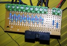
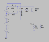
Precision resistors to divide the battery cell voltages down to less than 1.8 volts. For my 24 volt battery I used 0.1% 15ppm/C resitors from Element14, in particular 33k2 Resitor and 2k49 Resistor which gives me a division ratio of 14.33, so 24 volts becomes 1.674 volts
To balance the current through each cell some 1% 1/4 watt resistors, I chose these from Element14 TE CONNECTIVITY - LR0204 series resistors. The values are in the spreadsheet and on the circuit diagram.
Prototyping Board or Breadboard to mount the components and hookup wire available from Adafruit, your local electronics shop, ebay etc
Connectors, wire and hardware to connect your battery terminals to the Prototyping board. For the wire connecting the battery terminals to the board i would use some fine wire like 24-26AWG hookup wire so if you do have a short the wire will vapourise without causing a disaster. The exception is the battery minus lead which should be larger than 18AWG.
0.1uF ceramic filter capacitors from local electronics shop etc.
Power supply to run Beaglebone, I used something like this Switch mode supply
Secondly you will need to make up the resistor divider board
This is done as per the circuit diagram, the ADS1115 A/Ds, can either be placed on the resistor divider board which is now my preference but not the way I made my first unit or on a Beaglebone Protocape or equivalent
Next we connect it all together
Set the power supply voltage output to 5 volts. Connect to the Beaglebone via the 'Cape Expansion Headers' connector P9 pins 5 and 6. The Beaglebone negative (DGND P9 pins 1 and 2) and the power supply negative should be connected directly to the resistor divider board to avoid ground loops. There should only be one negative wire back to the battery negative terminal.
If you have put the A/Ds on the resistor divider PCB the connections back to the Beaglebone via the Headers will be I2C2_SCL on P9 pin 19 and I2C2_SDA on P9 pin 20 and the 3.3 volt power supply to the A/Ds on P9 VDD_ADC on P9 pin 32.
When all the other connections are done the power supply can be connected up to the battery positive supply via a fused circuit. It might be worth putting a switch on the positive supply so you can turn the Beaglebone off.
Software
Connect the Beaglebone up to your computer and SSH to it, if you are not sure how to do this do a google shearch "SSH Beaglebone". Adafruit has some good tutorials on getting started with the Beaglebone.
If your Beaglebone has access to the internet you can download the software with the command "git clone https://github.com/simat/BatteryMonitor.git"
Change directory to where the code has been downloaded to "cd BatteryMonitor"
Copy the appropriate config file and name it "battery.cfg". Copy the appropriate starting summary file and name it 'summary'
Start Python "python"
Load the Battery Monitoring software "import batteries"
Start the Battery Monitoring deamon "batteries.deamon()
You should see output from the deamon showing you the battery voltages.
The deamon can be stopped by typing ctrl-C
Then you can exit python by typing ctrl-D