Venom LiPo charger PSU repair by Amberwolf

amberwolf

Administrator
Staff member
Joined
Aug 17, 2009
Messages
42,472
Location
Phoenix, AZ, USA, Earth, Sol, Local Bubble, Orion
file.php


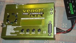
This charger/PSU from SoSauty died with no output from the 12V PSU. The charger appears to function when powered off my 12V lighting NiMH pack on CrazyBike2, though I haven't verified it's operation with batteries connected.
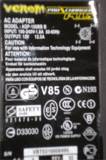
DSC04318.JPG
DSC04335.JPG
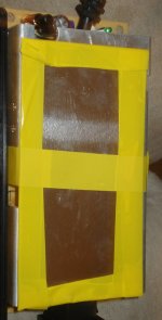
The first challenge was opening up the PSU case, because my special driver bits that would've fit these screws
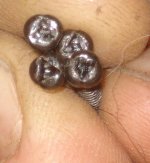
DSC04317.JPG
were lost with my bike toolkit earlier this month. Had to dig around to find a flatblade driver bit that would fit inside the little triangular hole in the screws tight enough to drive them but deep enough to not slip; took nearly an hour of digging around because of my leg hampering me getting to a lot of stuff ATM.

Immediately smelled cooked electronics once opened, most strongly down at the AC input end, particularly at the fuse. But neither fuse nor NTC are damaged or open.
View attachment 5

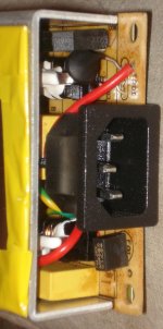
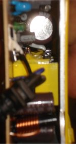
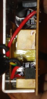
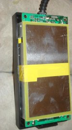
Some internals pics:
DSC04319.JPG

DSC04320.JPG

DSC04325.JPG

DSC04328.JPG

DSC04330.JPG

DSC04333.JPG

Interesting that this PSU has two separate AC input sections, only one of which is populated at all. Not sure why it's made this way, as I didn't try tracing anything out to see if it's just maybe separate sections for higher current output, or two different input voltages, or what. Neither idea makes much sense to me, but all I could think of ATM.

One thing that looks dumb is that the main AC side cap is secured down so that it has nice solid heatsinking contact to a pair of higher-wattage resistors (taht presumalby get pretty warm, given their size), as well as the screw of the heatsink for one of the switching FETs, and some other components. Can't be good for the cap's lifespan, but since the charger is sealed with no ventilation it's probably moot anyway.

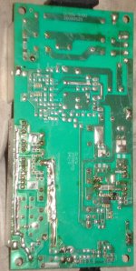
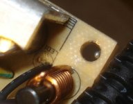
Only obvious problem I found visually is that there are solder blobs stuck to the PCB in various places, presumably from manufacturing. None appears to be in a position to short anything, but that doesn't mean there isn't one on the component side doing that. You can see a large one in teh screwhole here:
DSC04334.JPG

As a side note, they only used three wires in the output cable. Two of them are on the positive output, and one on the ground.
View attachment 2
All same gauge wire, so dunno why--it's pointless to have the second positive since the return ground wire can't handle any more current than a single positive. The end connector that goes to the charger is wired two positive and two negative, according to the diagram on the label (pictured a bit above).

Continuity check across the output connector shows a dead short both ways, and ohm readings 10ohms one way and 23ohms the other. Something's shorted in the output stage, will have to unsolder the heatsinks to get under them to see more. Got bunches of other things to get done today, so this is all for the moment.
 
FWIW, I expect their stuff is identical to most of the other stuff like Hobbyking's, just with different stickers and paint jobs. Probably even from the same factory in China. :lol:

Anyhow, I expect that the failure of this PSU is heat-caused, and is probably the output FETs but I have to t/s more after I open it up further.
 
Metallover said:
I can't contribute to your repair, but in the RC world Venom has a bad rep for crappy products,, especially batteries. It doesn't surprise me something they sold failed.. :(

It was a 7.2V Venom NiMH pack that blew up in my workshop... spewed carbon dust everywhere (including $50,000+ logic analyzer)
 
amberwolf said:
Interesting that this PSU has two separate AC input sections, only one of which is populated at all. Not sure why it's made this way, as I didn't try tracing anything out to see if it's just maybe separate sections for higher current output, or two different input voltages, or what. Neither idea makes much sense to me, but all I could think of ATM.
Normally I'd say there was a 115VAV input and a 230VAC input, but it's a universal-input supply. Weird.


amberwolf said:
As a side note, they only used three wires in the output cable. Two of them are on the positive output, and one on the ground.
All same gauge wire, so dunno why--it's pointless to have the second positive since the return ground wire can't handle any more current than a single positive. The end connector that goes to the charger is wired two positive and two negative, according to the diagram on the label (pictured a bit above).
My guess is that they doubled up one of the connections to reduce the voltage drop along the cable. Though I would have doubled up the ground instead.
 
Yes, well, that's what I meant with my overly-wordy and poorly-chosen phrases. :) It doesnt' do much good to double up just the positive line if you don't do it for the return, too, right? (especially since they have the PCB pads for two wires on each one, and pins on the end of the connector for them, it's obviously SUPPOSED to have all four)

I'm hoping to get back to this tomorrow or maybe tonight to check if the cable itself is the source of the short, by desoldering it from the PCB, before I unscrew and unsolder the heatsinks to get to the rest of the components.
 
Some inside pics of the Venom charger itself, while I had it open to fix a problem I created: I was trying to figure out the menus, and it slipped out of my hand; I grabbed it before it hit the floor (not far a fall from the wheelchair anyway) but I somehow hit the first two buttons hard enough to crack the button stems off from the switches inside:
DSC04358.JPG
I'll have to glue them back on later, as I was too shaky-handed to do it by the time I got the screws off the end panel to slide it apart.

I also figured while I was in there I'd fix the alternate 12V (11V-18V) DC input, whcih is those two little clear-looking stubs of wire on the input (left) side. From what I could see, they were the bit left on there when the car-battery clips were cut off of it (but left in the box with it); I decided to reinstall them since I have some 31Ah 12V SLA I can use as an alternate power source while experimenting with this thing, until I can fix the 12V PSU that came with it.
DSC04355.JPG
You can see the pads for the 12V clips just under the black and white wires to the powerswitch, at the bottom fo this pic. I'd already desoldered the stubs of wire from the pads.

One bit of poor assembly I noted while in there is the FETs are plastered with a huge amount of thermal paste, and it is probably water-based as it is pretty much dried out already. If I end up using this to do any charging or discharging, I'm going to redo that paste completely.
DSC04356.JPG

A pic across the shunt resistors, under the LCD to show the rest of the component side of the PCB
DSC04360.JPG

The PCB marking:
FS-BC8
VER 1.0
08/05/20
DSC04361.JPG


When I finished, I tried to set it up on my laptop via USB, but even though the laptop detects the charger and does install teh drivers, the VEnom program itself doesn't seem to talk to the charger--not only does it not read any cell voltages, but it doesn't even read the charger's settings, which it appears it should be able to do.

I hooked up the most negative balance taps from the Vpower pack to the charger's balance connector, and just the negative from the pack, and set it to 7s, since the tap has seven wires. Theoretically that should give it the ability to read those first cell groups, but apparently not. No error messages, but no voltage readings either.

I did not attempt to start any charge or discharge operations, as I don't want to do anything other than monitor the cells while the bike does the discharging, but I suspect that I'd have to have it doing some operation via the charger before it would send any data to teh PC. :(

Maybe I'll contact Venom and see if they A) will answer and B) have a clue what I'm asking for. ;)
 
Hey Amberwolf,

I have another idenical Venom charger/power supply in which the power supply died. Doesn't seem to like 5amp (actually a 10amp pull from supply) 24V charging with 6S! A few hours of persistent charging and fttt. . .

Replaced the power supply with a reputable one and the charger works well enough. Don't' understand why the basic RC chargers can't be set to charge say 4.1V rather than 4.2 volt? My other power supplies come with a fan.

Best to ya,
SoSauty
 
Given that the PSU part appears to be no ventilation, and pretty small parts, I'm not surprised it fails at higher power levels, especially sustained ones. Plus having all the metal plating around it to reflect heat back into the electronics rather than let it out doesnt' help.

I expect the parts used are also run at their top end of specs, as so many things seem to be nowadays (really, for the last decade or two, whereas many things used to have some overhead room left above usage points).

I still have had no time to go back to this (or most other projects), but eventually I'd like to fix this. Once I do, you can apply the same fix to your more recent blown PSU, and it will likely take care of it, as I'd expect the same things to fail.
 
I got back to this tonight, because I wanted to use the Venom to charge some NiMH that's the wrong nubmer of cells for any of my regular NiMH chargers, but I dont' have a PSU to power the VEnom except for SLA (and I'd rather just use a PSU direct).
DSC04869.JPG
So I poked around and found two parallel .27ohm resistors taht read open, and have some of their coating blown off (presumably from evaporated wire-wound resistor material).
DSC04868.JPG
They appear to be current sense resistors or emitter(or source) resistors for the switching transistors on the primary side of the SMPS. Most likely the transistor are blown (shorted) but I haven't measured that yet. Can't seem to hold the soldering iron and sucker well enough to get them off the PCB without destroying some SMT resistors nearby, so maybe later when I'm nto so tired.

They are probably these:
http://www.alldatasheet.com/datasheet-pdf/pdf/60928/FUJI/2SK2645-01MR.html
 
I just checked; no it's 11V to 18V DC.
 
FOr now I'm running this off an SLA I topped off over the last few hours; it seems to be working, but it doesn't have a way to tell it how many cells except for discharge, so I assume it's simply going to watch the voltage change to know when to end it. I guess I'll have to watch it manually to be sure.

I started charge at 3A about 15 minutes ago, and am monitoring thru a Turnigy Watt Meter, to compare accuracy of the two. So far, at the least the current is questionable, as it reports 3.0A in the Venom, but only 2.45 on the TWM (whcih I know is reasonably close to accurate, enough to trust this reading). Voltage appears identical on both.

I have no idea if the temperature sensor will work, becaue I'm using the one in the pack, a two pin, connected to two of the three pins on the Venom. Not enough info on there to tell me if it's even the same *type* of thermal sensor it expects, and ntohgin int he menus to alter the settings for that, other than the overtemp cutoff point, which defaults to 52C.
 
WEll, after 21 minutes it reported FULL at about 0.7Ah put in (per the TWM), about .9Ah per the Venom. Venom showed 17.3V, while TWM showed 16.4V. I checked with a separate DMM for voltage, and got 16.4V. I dunno about the Venom's accuracy there--it's not even consistent with itself! :roll:

Anyway, I have no idea if it's actually charged fully or not; I suspect that the two addon cells are not, because it never went thru the heating/balancing stage at all. I'm gonna have to charge those two sticks separately just to be sure.

If I put my 50W car headlight on there, it is absolutely definitely brighter, and whiter light, than with 10 cells. It also uses more like 68W, per the TWM.

The voltage does drop to about 14.2V, then when I disconnect the headlight it's back up to about 15.9V. I did not yet measure each 2-cell stick under load (but they are all within a couple hundredths of a volt when measured without a load).

Turn signals and brake light bar operate ok at this voltage, too. LED bar appears about the same brightness (it might have a regulator in it), but the turn signals are notably brighter, and consume more current--3.4A vs 2.8A per pair.

Crossposted to CrazyBike2 thread.
http://www.endless-sphere.com/forums/viewtopic.php?p=465143#p465143
 
Since I figure I used up at least 2 or 3Ah on the NiMH pack for lighting on day-before-yesterday's ride, I thought I'd recharge it and see what happens. So I set up the Venom on the SLA again, monitoring with the TWM again.
DSC04885.JPG

This time I set the Venom to it's max of 7A charging, but the TWM only shows a max of 5.2A. Voltage is also off by as much as 2V, lower on TWM. Measuring voltage drops on the cabling doesn't show more than a couple tenths of a volt, which doesn't reconcile with either the voltage or current differences. I guess the Venom just isnt' anywhere NEAR accurate. :roll:

TWM showed about 5Ah put back in; teh NiMH did finally get a little warm, but only barely. So it is not really balancing yet. I might have to drain the original 10 cells down to whatever level the 2 addons are at, then try again, or manually charge those two and use the 10-cell charger on the originals, ot get them all more or less balanced.
 
I've been trying to find out how to get the USB logging functionality to work, but so far no luck. I did hoever fined aaatht this is a cloen of the Bantam BC-8 (it may actually BE the SAME unit inside, given the PCB markings above, just wrapped in a differently-painted casing, with firmware edited to show Venom insead of Bantam).

http://www.rcgroups.com/forums/showpost.php?s=06385833b6a73c985883ce3454688d20&p=10519206&postcount=14
http://www.rcuniverse.com/magazine/newproduct.cfm?product_id=1466
 
fixed usb, was bad cabvle:
http://www.endless-sphere.com/forums/viewtopic.php?p=520385#p520385
 
found that venom charger will work with logview using bantam bc-8 setting. ;)

logview doesn't list venom at all
http://www.logview.info/vBulletin/content.php?31-devices
but it works cuz the venom is a bc-8 inside.
 
Venom still working ok with SLA as the input source.
http://www.endless-sphere.com/forums/viewtopic.php?p=535912#p535912
 
Found some bugs in LogView, using with the Venom. Causes data loss! Can only save one log before you have to close and reopen Logview, or else any subsequent logs will be saved as the new file but with the old file's data. :(


Using Venom to discharge and recharge an experimental pack I was using for 12V lighting pack, and accidentally left plugged in while at work, and someone turned on my lights and discharged it to zero volts. :shock: Since it is not an RC LiPo pack I decided to risk recharging it, and so far ti hasn't blown up. :lol:

http://www.endless-sphere.com/forums/viewtopic.php?p=571610#p571610
 
Back
Top