VESC Wiring single regen brake for dual motor?

Jidobaba

100 µW
Joined
Aug 14, 2021
Messages
8
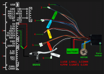
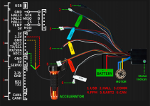
I have a diy vesc build(makerbase 75100) for my rear motor. Front motor is a generic 350w m365 clone controller. So, I want to have the regen brake on the vesc paired to the same brake lever on the m365 controller. It's a separate system (2 controllers, 2 motors, 2 batteries, 2 throttles). Brake line has 3 wires(5v, gnd, signal).
How do I make the connection to the Vesc brake line? I'm thinking signal and gnd , or 5v and signal with a diode between the 5v line?
Any help is welcome as I'm stuck here guys!
 

Attachments

  • -1088311065-2108711989.png
    -1088311065-2108711989.png
    95.2 KB · Views: 4
You'll need to have a common ground between the systems if you want to use a single signal to activate / control both.

The signals would also have to be connected together.

The 5v that powers the lever's sensor should only come from one controller, for any direct 5v connection, or else you can cause problems with the 5v regulator in one or both controllers. But if you need the sensor to work even if only one of the controllers is powered on, then you can install a diode in both 5v lines to prevent feedback of either controller's 5v back into the other one. This may (shouldn't, but could) affect the output voltage of the sensor, so you might have to recalibrate the controllers' input ranges to compensate.
 
^ thank you! So, Gnd + signal. I'll go this easier way, Do you think the Gnd should be connected together battery-side? Or any Gnd pin on the secondary (vesc) controller board will do? I would use the single Gnd pin at the connector but that's also used for accelerator so I don't know..
 

Attachments

  • -1088287444-2081994878.png
    -1088287444-2081994878.png
    102.3 KB · Views: 2
It shouldn't matter, but probably the one that sees the least current on it (so not the battery ground) will affect operation least. So I'd try first just with the brake sensor's ground, and unless you have problems with that, don't worry about it. There shouldn't be a problem sharing the throttle's ground (the currents are so low for the sensors that even a shared tiny ground wire should be sufficient).
 
It shouldn't matter, but probably the one that sees the least current on it (so not the battery ground) will affect operation least. So I'd try first just with the brake sensor's ground, and unless you have problems with that, don't worry about it. There shouldn't be a problem sharing the throttle's ground (the currents are so low for the sensors that even a shared tiny ground wire should be sufficient).
Will get to it but so happens I have another (more pressing) issue!
I run motor detection on the vesc and the motor does the spinning and says setup success. But when I try to run the fwd/rev test to finish up the wizard, motor just shudders and won't spin. When I turn the motor by hand but there's resistance and I notice that the vesc lights up green from blue. I swapped out hall wires and restarted the wizard, same situation. Spins up fine in motor detection but stuck after. I have googled and no one seems to have had my exact problem. So frustrating.
 
But when I try to run the fwd/rev test to finish up the wizard, motor just shudders and won't spin. When I turn the motor by hand but there's resistance and I notice that the vesc lights up green from blue.
There's some odd control combinations that can produce this with a VESC, specifically if you have some form of control setup (like ADC) and it's in, like, a duty cycle mode. If that's the case, the test system and that code seem to fight about what the motor position should be -- namely, the control app is saying "motor should be stopped" and test app is trying to force it go. This also seems like it's the case since you're getting resistance (active braking in a duty cycle app mode) when trying to spin it by hand.

Go into the "App Settings" -> "General" and set "App to use" to "no app" to fully disable any of the controls.
Thank you for the reply. I'm out now and obsessing over it still. Swapped around the phase/hall wires, changed max current, voltage, k,p,i,lambda, duty cycle values etc all day and I'm just about burnt out. I'll try out your post in a couple hours but it does seem odd since I hadn't even got to adc/input setup and it does this.
 
There's some odd control combinations that can produce this with a VESC, specifically if you have some form of control setup (like ADC) and it's in, like, a duty cycle mode. If that's the case, the test system and that code seem to fight about what the motor position should be -- namely, the control app is saying "motor should be stopped" and test app is trying to force it go. This also seems like it's the case since you're getting resistance (active braking in a duty cycle app mode) when trying to spin it by hand.

Go into the "App Settings" -> "General" and set "App to use" to "no app" to fully disable any of the controls.
Update: just tried it now - set to App to use to 'No App' on the PC tool and android app, I'm still getting the same problem unfortunately.
 
Back
Top