VIDEO Crystalyte 72v60a Controller - Strange Throttle Issues

Joined
Jan 8, 2010
Messages
36
Hello all,

First off I want to say I spent a fair amount of time searching this forum so if the answer was out there I do apologize for the unnecessary post!
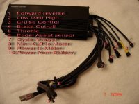
Setup:
5305
72v 60a 18FET (4110)
18s2p Turnigy 5000mah 25c
Half twist throttle
CA 2.2

I set the CA to 10a limit and left everything else alone. Hooked up the throttle and...nothing. This is where it gets fun of course. In my frustration I kept playing with the throttle and eventually the motor spun up, but only if I kept "pulsing" the throttle. It's almost like the pedelec and throttle connectors are switched and I have to keep simulating rotation to keep the motor moving. The speed of the motor is almost directly proportional to the frequency of my "throttle pulses" (0%-100%-0%-100% etc movement on the half twist).

I couldn't seem to find any posts relating to this sort of problem but then again I might just be using all the wrong words...

If anyone's got some input to this problem please let me know.

EDIT:
I did check the throttle wires.
At the board 4.35v
No throttle .86v
Full throttle 3.68v
Same result with or without the C.A.
Added Video

[youtube]zLWrSvrQCek[/youtube]
 

Attachments

  • IMG_4418.jpg
    344.5 KB · Views: 2,952
rechargeourfuture said:
Hello all,

I set the CA to 10a limit and left everything else alone. Hooked up the throttle and...nothing. This is where it gets fun of course. In my frustration I kept playing with the throttle and eventually the motor spun up, but only if I kept "pulsing" the throttle. It's almost like the pedelec and throttle connectors are switched and I have to keep simulating rotation to keep the motor moving. The speed of the motor is almost directly proportional to the frequency of my "throttle pulses" (0%-100%-0%-100% etc movement on the half twist).

what happen if you remove C.A. from your current configuration? Will you able run the motor smoothly? Why did you limit to 10a, when you have 60a controller? I mean why so low, why not 30 or 40amp limit?
 
Same result with or without the CA. The 10a limit was just to be during bench testing. I had planned on doing a load test and wanted to 'step it up' to observe how my first experience with china lipos would play out. Been a thunderpower guy before all this E-bike madness found it's way into my life :D . I do plan on keeping it around 20a while I put some miles on the new pack before relying completely on this new hobby of mine to be a primary source of transportation :mrgreen:
 
rechargeourfuture said:
Same result with or without the CA. The 10a limit was just to be during bench testing. I had planned on doing a load test and wanted to 'step it up' to observe how my first experience with china lipos would play out. Been a thunderpower guy before all this E-bike madness found it's way into my life :D . I do plan on keeping it around 20a while I put some miles on the new pack before relying completely on this new hobby of mine to be a primary source of transportation :mrgreen:

You should proceed the following to narrow down the issue(s):

1. Test the motor with another controller
2. Remove the CA and test the controller with another motor
3. Check the HVC on your controller (HVC = High Voltage Cutoff) with your seller/vendor had set to
4. Use another set of 72v battery
5. Check throttle with another controller
6. Check phase & hall wire arrangement and see if they are sequential
7. Ask the seller for help and how the controller was programmed

Let me know if you need more help. Either PM me or reply here. :)

Regards,
Lyen
 
Thanks for the Advice Lyen. I've added a video to help with the description of this problem. I wish I could test against other equipment but unfortunately I only have this one battery, controller, throttle, and motor. This is as much as the wallet allows. I'll have to check into the HVC. This controller was purchased from a great fella Maxwell65 here on the forum, so I will have to check with him. As the video will show, when the motor is spinning it appears to be operating normally. I don't know if that completely rules out the motor's hall sensors but my guts would tell me yes.

Are there wiring diagrams for this controller out there? I peaked around Google for a bit but only came up with older models. The day I got the controller I carefully inspected the board and cleaned off many a small solder ball. All the wiring looked to be soldered securely as well.
 
rechargeourfuture said:
Thanks for the Advice Lyen. I've added a video to help with the description of this problem. I wish I could test against other equipment but unfortunately I only have this one battery, controller, throttle, and motor. This is as much as the wallet allows. I'll have to check into the HVC. This controller was purchased from a great fella Maxwell65 here on the forum, so I will have to check with him. As the video will show, when the motor is spinning it appears to be operating normally. I don't know if that completely rules out the motor's hall sensors but my guts would tell me yes.

Are there wiring diagrams for this controller out there? I peaked around Google for a bit but only came up with older models. The day I got the controller I carefully inspected the board and cleaned off many a small solder ball. All the wiring looked to be soldered securely as well.

I have just finished watching your video. It seems the issue is either your controller or the throttle. You should able to simulate the throttle function by try shorting red & green wire on the controller throttle wire. It would also helps if you have a 10k or less resistor handy and attach between the +5v and the throttle line to prevent damage. The red should be +5v lead and the green is the throttle engage lead. This way, you can tell if the motor can force to spin immediately or not when full throttle is engaged. If it does, then the issue is very obvious on the throttle itself. If not, then it is between the controller and the motor. :)
 
i don't have one of these boards handy to check. but from memory the pedal sensor thingie connects to the board via a pad labeled (XS+) and the throttle goes to one beside it labeled (SP). in most cases where both the PAS connector and the Throttle connector are provided the Throttle was usually a 4pin (for use with a throttle that has the battery level indicator) and the PAS used a 3 pin. the PAS pedal sensor ouputs a pulsing signal. the motor is supposed to pace itself with this pulsing.

i could be totaly out to lunch on this, but i can see 3 senarios to explain this action. i assume that you have a throttle with a 3 pin connector.

#1 the (XS+) and (SP) pads on the board are separate circuits and not connected together on the board. you have a 3 pin throttle connected to the PAS connector and not the 4 pin throttle connector. pulsing the throttle would then act like the pedal sensor and let the motor run.

#2 the (XS+) and (SP) pads on the board are separate circuits and not connected together on the board. the controller does not have a 4 pin connector and ONLY has the 3 pin PAS connector that you have connected your throttle to. pulsing the throttle would then act like the pedal sensor and let the motor run.

#3 the (XS+) and (SP) pads on the board are the same circuit connected together on the board. somewhere else on the board there is a jumper that defines whether the controller works as a PAS or as a Throttle type. i hvae no clue where that jumper would be.


rick
 
Lyen, I bridged the x5v (red) and throttle line (green) with the 10k resistor and shorted the two wires, nothing. Now if I simulate the same on/off/on/off pusling with my jumper leads the motor will spin up just the same. So definitely a controller-motor issues here. Thanks for the tips.

Rick, I'll have to take a peek inside it again to check that out. I'll make sure to take pictures. Thanks for the info.

Here's a picture from my supplier identifying all the connectors. My half twist throttle is indeed a 3pin.

Just in case someone who was doing their research found this page I want to point out that Max (maxwell65) is a GREAT guy with GREAT prices. These items arrived to me wrapped up in perfect shape ON TIME. Do not hesitate to buy from him. The problems I'm having are due to the fact that I bought a CHINA controller instead of a name brand one. I accepted that fact there may be some extra "work" involved before things operate smoothly.
 

Attachments

  • Controller wire diagram 99kb.jpg
    Controller wire diagram 99kb.jpg
    48.7 KB · Views: 2,865
Alright, here's a quick shot of the back with a *very* crude wiring diagram. I don't see an XS+ but there is an SP and the Pedal Sensor wire goes right to that oddly enough. The grounds for the two sensors are different but the voltage source is the same. Thoughts?
 

Attachments

  • Crude Wiring Diagram.jpg
    240 KB · Views: 1,043
rechargeourfuture said:
Alright, here's a quick shot of the back with a *very* crude wiring diagram. I don't see an XS+ but there is an SP and the Pedal Sensor wire goes right to that oddly enough. The grounds for the two sensors are different but the voltage source is the same. Thoughts?

Here is the quick shot of the Lyen's edition 18 FET controller (http://endless-sphere.com/forums/viewtopic.php?f=31&t=16605) below. I see quite a few things missing and/or absent but unable to disclose due to proprietary information. Perhaps that is the way the seller had requested from the manufacturer.
http://img101.imageshack.us/img101/3497/img8079.jpg

The next thing you can do is test the hall sensor and/or wiring to the motor.
1. Mount the motor onto the true stand or a fork standing up side down and secure the motor and nuts
2. Connect the throttle back to the controller
3. Connect the motor phase & hall wires to the controller
4. Power up the controller
5. Turn the throttle half way and hold the position
6. Spin the wheel with your hand. Be careful the motor may spin and jump off the stand
7. If the motor gives you some kind of movement, then that means the hall sensor & wire and/or controller hall input circuitry has not receive all the spinning sequence data from the motor. Therefore, you are half the battle. :)

Your truly,
Lyen
 
Well after some deep searching I managed to find a few pictures from other members with the same board. I have to say I'm more confused than ever about what board I have here, but the good news is I figured it out...well Rick did really.

Turns out his first guess was right too. The picture labeling the connections has 5 and 6 reversed. The 4 pin connector IS the throttle and the 3 pin is the Pedal sensor. After all the searching to help confirm this theory with pictures of homemade boards (Lyen, methods, etc) I hacked my 3 pin throttle to the 4 pin for testing and it works great. The throttle was limited to something like 75% of what I was getting through the Pedal Sensor port until I plugged in the LHM switch (should read LMH?). I get 100% throttle with the switch at the "M" position (should be H). Ahhh China's Mysteries....

Now Lyen when you say missing....
 
after years of trying to decipher manuals written in many foreign lands i am able to read perfect EngRish. not to be confused with a vaguely similar language - English.

the (XS) pad is what is used on the Crystalye V2 Controlers using the Cypress PSoC controller chip. when i saw the photo it looked like the Crystalyte controller. so i assumed wrong. see that clearly now that i saw a picture of the board.

but the unmarked 4-pin throttle and 3 pin PAS connectors being confused with a 3 NOT 4 pin throttle was an issue with some of the early Crystalyte controllers.
made a bunch of 3 to 4 pin throttle adapters for that particular dealer.

rick
 
My system behaved in a roughly similar manner when one hall sensor wire was not connected.

However mine would run for 2 seconds from a dead stop, unlike this one. Pulsing made it go too.
 
most controllers have a system that checks the hall signals. if one of the halls fails and does not switch while the others do the controller will error out and shut down. when you release the throttle all of the halls stop switching which is normal for a stopped motor and will clear this error condition.

rick
 
hi everyone,maxwell65 here,

i just found out about the issues with the controller as one of my other clients found this posting about it and asked for my help,otherwise i would not have known.

first to rechargeourfuture,i really appreciate the fact that your so nice about the whole experience, i have another client who about 2 months ago told me he could not get the controller to work,he too was very patient but in the end as we could not find the problem i had him send the controller back to clyte and he bought another controller from another vendor and asked for a refund in an email he sent,i agreed immediately and told him that he would however absorb the cost to ship the controller back as i was sure he may have blown it himself through negligence(however i always give the benefit of doubt ).but now im sure he had the same issue and i have every intention of refunding his shipping cost (as well as of course the controller he returned),i told him to send the tracking # as soon as he sent it,however he sent it out as regular mail as it would cost $50 to ship with the track# and $25 without,he sent it back about 2 weeks ago and as far as i know it still has not been received by clyte,now i will have to pay him back weather clyte gets the controller or not as it's the right thing to do.

BTW that guy rick is some sorta genius as for his diagnosis on that issue,i read what he wrote and was blown away by his prognosis,at first i had no idea what the hell he was talking about,and at first read i thought "this guy is out of his tree", but then when rechargeourfuture wrote you solved the mystery, i thought,"i gotta read this nuts "rick" post again", then as i was reading his prognosis i thought,"this guy is friggin einstein or sumpin", and to think i thought i was a smart guy! :shock: thank you rick!!!and thanks to lyen and methods and steveo who has graciously given their time to help other people with issues on stuff that i have sent out,you are all truly selfless and great individuals.and make no mistake i believe you guys are geniuses as well.hope im not forgetting anyone.

so far i know of 3 people that have suffered with this issue,and all will be resolved to their satisfaction,i am in contact with clyte and we are working to make sure this will not happen again,rest assured that i strive to only send out quality product ,and from now on before any controller or motor leaves my shop,it will be tested by me.

again thanks to all
max
 
Just wanted to point out that in THIS situation there really is nothing "wrong" with the controllers. It's just an issue of incompatibility between different "versions" of controllers and throttles. Some throttles have a battery meter built in which requires a 4th wire, hence the 4pin connector on the controller. Some throttles do not have a battery meter built in so there are only the 3pins.

Very simple fix to a very simple issue. My controller is working great and I couldn't be happier.

Thanks Max for the good service! Thank you rick for your help in fixing this particular issue.
 
WHy is the video private? :?:

I have the same issue, I experienced it today, I got one 72v 50A controller from Max, and two throttles: a half motorbike throttle, and a LHM .

When I connect up the motorbike style throttle, I get the same problem: no response.

I was messing with the throttle, flicking it back and forth quickly in aggravated fashion when ALL OF A frocking SUDDEN this massive X5304 SURGES and starts to pull itself free from the Parks Stand I had it "secured" in.

Thankfully, it ran out of "throttle" before I ended up with any more problems than I already have.

So.......do I now need to go and buy a new throttle to make up for this incompatibility?

Cheers.
 
rechargeourfuture said:
Well after some deep searching I managed to find a few pictures from other members with the same board. I have to say I'm more confused than ever about what board I have here, but the good news is I figured it out...well Rick did really.

Turns out his first guess was right too. The picture labeling the connections has 5 and 6 reversed. The 4 pin connector IS the throttle and the 3 pin is the Pedal sensor. After all the searching to help confirm this theory with pictures of homemade boards (Lyen, methods, etc) I hacked my 3 pin throttle to the 4 pin for testing and it works great. The throttle was limited to something like 75% of what I was getting through the Pedal Sensor port until I plugged in the LHM switch (should read LMH?). I get 100% throttle with the switch at the "M" position (should be H). Ahhh China's Mysteries....

Now Lyen when you say missing....


So what I need is a 4 pin throttle and not the 3 pin that came with the throttle?
 
you just need to rewire the throttle with a 3 pin connector. pin1 on the 3 pin goes to pin 1 on the 4 pin. pine 2 goes to pin 2 and pin3 goes to pin 3. ignore pin 4. do not use pin 4 at all. pin 4 has the full battery pack voltage. and full pack voltage, even if only for a nano-second will kill a hall type throttle.

the connectors are the JST Manufacturing SM series. they are available at many distributors including Farnell's

rick
 
rkosiorek said:
you just need to rewire the throttle with a 3 pin connector. pin1 on the 3 pin goes to pin 1 on the 4 pin. pine 2 goes to pin 2 and pin3 goes to pin 3. ignore pin 4. do not use pin 4 at all. pin 4 has the full battery pack voltage. and full pack voltage, even if only for a nano-second will kill a hall type throttle.

the connectors are the JST Manufacturing SM series. they are available at many distributors including Farnell's

rick

Thanks Rick I am looking into that now. PS Farnells are expensive people!
 
You could just cut and solder.
 
Back
Top