Voicecoils's 2nd build: Giant DH Team

voicecoils said:
Thanks Mark. I don't see it on the T7 website.

They do have this one:

http://www.torpedo7.com.au/products/PLTOONNUG/title/PROLINE-Shimano-UG-Freewheel-Removing-Tool
It looks long enough and I can grind down the sides. Bit of a PITA but for $8 I can't complain...

Can you remember if your tool was a BBB (triple b) or Super-B tool?


Sorry, Super-B.

It came in this kit (which I got on sale and is fantastic...crap quality, but still fantastic).
http://www.torpedo7.com.au/products/SBTOKNN95/title/SUPER-B-Bike-Tool-Set---96500


It needed turning down. You could do it with a file....and a lot of beers..
 
More mini updates:

picked up the appropriate freewheel tool at a bike shop and spent some time with a drill, vice, files and dremel opening the back hole and taking down some material off the outside to get it to fit.

now the new 5 speed shimano freewheel is fit.

I've drilled my 24" rim to fit the 12ga spokes and hope to lace it up soon. After that, I need to test the spacing in my DH Team swingarm and make up a 'c' spacer to keep the phase and hall wires from getting diced by the disk brake rotor.

Oh, and an Infineon 18fet controller is headed my way ;) Looking forward to 65+A battery side discharge capability :twisted:

6993854.jpg
 
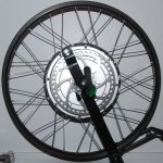
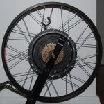
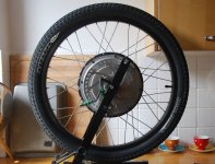
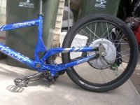
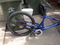
Finally, months after receiving my FREE 5304 it is at last in a new wheel. It's now in a 24" Alex DM24 dirt jumping rim. I had to drill the crap out of it to get the 12ga spokes to fit then drilled it some more to get them to fit at the necessary angle for the 1 cross lace necessitated by the spoke length. It's close to round and true now but it's a bit hard to tell on my cheap truing stand as it has to be stretched out so far to fit the X5 :shock:

24in5304_disk-side.jpg
24in5304_cluster-side.jpg

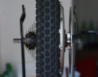
Next to do: figure out why the 5 speed cluster has a wobble, make the C shaped spacer to protect the wiring, put on rimtape and mount the tube and tyre!
 
Looking good, Most of the x5 cover plates have a bit of run out.


Is the wobble side to side or up and down?
Kurt.
 
Kurt said:
Looking good, Most of the x5 cover plates have a bit of run out.


Is the wobble side to side or up and down?
Kurt.
Cheers!

The wobble is side to side, so the largest cog comes closer to the side cover on one side then on the other.

I'm just hoping that I didn't screw it on cross-threaded and muck up the sidecover threads :shock:
I need to file my cluster extractor tool out a bit more to remove the 5 speed cluster. The 8 speed cluster sat out farther so the cluster extractor tool worked fine for that one.
 
What's the latest VC? I'm doing a similar build, also hoping to get the batteries into the frame. I was hoping to go 20s10p konion cells, but I'm getting them too slowly. Might also go for headway cells in the meantime for the 5305 I've ordered. I'm very keen to see your battery box if you have some pictures.
 
patrickza said:
What's the latest VC? I'm doing a similar build, also hoping to get the batteries into the frame. I was hoping to go 20s10p konion cells, but I'm getting them too slowly. Might also go for headway cells in the meantime for the 5305 I've ordered. I'm very keen to see your battery box if you have some pictures.

More details will be coming down the pipeline in about a month. I'm focusing on the end of my Uni semester at the moment.

The batteries will held inside the frame triangle with aluminium 'covers' in a pressure fit. The frame will locate and retain the batteries in the direction of motion while the covers will keep them from shifting from side to side. It's going to be a tight fit and the cells need to be protected. Under the thin blue shrink wrap, the cell bodies are 'live' so some thin padding/insulation will be necessary.

Good luck with your build! Perhaps you can use a smaller number of paralleled konion cells to run in parallel with headway cells if you plan to run very high current.
 
nice 8)

good luck with uni voicecoils, looking forward to the build getting finished up, should be sweeeeet :D

D
 
Nice looking setup, I'm getting a giant DH comp in the next couple days if all goes well to do a similar conversion, just no hub motors for me. That why this frame design is awesome for the conversion!

Sweet build, can't wait till its all finalized!
 
magudaman said:
Nice looking setup, I'm getting a giant DH comp in the next couple days if all goes well to do a similar conversion, just no hub motors for me. That why this frame design is awesome for the conversion!

Sweet build, can't wait till its all finalized!

RC build planned?

My DH Team frame has been SOLD to Mark_A_W and I will leave him to pick up on this build log if he chooses to down the track.

Had to make way for more projects and more bikes :)
 
I haven't got it yet.

And I haven't got a rear motor to suit.


So don't go holding your breath!!
 
No i'm using a nice big bmc 1500w 24v motor I plan on running at 36v. Two Stage reduction to disk mount in the rear. Once all the mounting is in place in working I will go to a Kelly controller. Current will be running 70a 36v
 
Ok TIME FOR AN UPDATE!!

I'm getting somewhere now...

- Motor: MAC Shanghai (BMC clone). It has a metal gear fitted but I fear it will be too noisy, may have to go back to 3x plastic gears.

- Controller: Infineon 18 FET (going to have to reduce the current or motor will fry).

- Battery: 60v nominal 10Ah Headways. 20 cells, 16 in a 48v pack + 4 booster cells. Thank god they fit...


I will have to use the Cycle Analyst to keep the current down from the 45-65A that the controller can draw. That will kill the motor...and my range (I'm incapable of "not" using the power).
I'm thinking around 30-35 amps will be fine....and have about 4x the torque of my current motor.


Currently planning wiring and a fibreglass battery box. The controller will go on the downtube (but reversed from the pic), the wires will be in the metal jiffy box, along with my DC-DC convertor for the lights.

Will be running 8" discs with Juicy 7 hydraulics, 56t front chainring, 7 speed rear, with a twist shifter fitted on LH grip and XTR derailleur.

Should be pretty close to my dream bike :twisted:

Getting help from Voicecoils and Full-Throttle - thanks guys.
 
:mrgreen: Looking very good. :mrgreen:

Great to see the headways fitted in the frame. Not much room left for the actual fibreglass box. Hope that works out.

Adrian
 
If you were willing to rebuild the pack completely, I think you would've gotten 24 headways into the triangle. I did and I think I had less space to work with. Headways will fit 3 cells next to each other without interfering with your legs or pedals.

You could have made a triangular pack like this:
<---------->
<----------><---------->
<----------><---------->
<----------><----------><---------->

Edit: I spaced these out but it doesn't seem to display on the thread, use your imagination ;)

Where each <----------> represents a 3 cells alongside each other. The key to saving space with the headways is to screw the negative of one cell directly into the positive of the other. Any chance you could measure the length of the bottom tube please? It would be pretty cool if you could fit 24 of the new 38140S cells inside the triangle for a 76.8v12AH pack.

I really like this frame, it's so clean, if I had to do another build this would be my likely candidate. Can you tell me what you did with the dropouts?
 
Ok, some more PROGRESS.

With Full-Throttle's help we lowered the LVC to 40v from 63v (ok, he did it, I watched), which will allow me to run either my 60v setup or 48v.


And we got the motor running on the bench. So now I can build it, and it will work.

Currently I'm working on a CAD model and then machining a foam core for a battery box.


And patrickza, with the MAC Shanghai motor, I really don't want 72v (24 cells). With 20 cells the no load speed will be 74km/h. The KV of the motor is too high for 72v. But, 24 cells would fit, just whack another block of 4 at the front. And no, I'm not reconfiguring the 24v pack, it's tab welded, not screwtop.

We tried a metal gear but it was very noisy. Not sure about that. Which means with plastic planet gears, I'll have to keep the current low...or peanut butter gears..


Here are CAD images of the quick and dirty battery models, next I will do the box around them.
 

Attachments

  • battery layout 1.jpg
    battery layout 1.jpg
    35.7 KB · Views: 1,048
  • battery layout 2.jpg
    battery layout 2.jpg
    29.8 KB · Views: 1,041
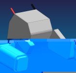
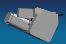
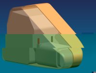
Ok, very, very rough model of box.

As you can tell, styled by an engineer (hey..the blends are conics!).


I'll get one of the industrial designers at work to take a look - they can "style" it for me :)
 

Attachments

  • box 1.jpg
    box 1.jpg
    24.2 KB · Views: 917
  • box 2.jpg
    box 2.jpg
    25.8 KB · Views: 1,048
Mark_A_W said:
Ok, very, very rough model of box.

As you can tell, styled by an engineer (hey..the blends are conics!).


I'll get one of the industrial designers at work to take a look - they can "style" it for me :)

Your not kidding. Looks nearly as bad as my effort. If you are going to let the ID guys loose on it, you might get a better result if they get there hands dirty and sculpt it on the bike. Can always them CMM it, skin it, so you get a nice symmetric model and then carve it out properly it on the CNC.

I want to see this looking slick. I am sure the ID guys will have some ieas on a nice paint job as well. I am sure Kon could do a nice caricature for you :D
 
Fair go, see how you go in 10 mins!


Actually, it's kind of limited. The back half is size for size with the battery. You can't increase the rads, or shape the side walls.
 
looking great Mark!

What are your plans on access into the box and frame attachment?

What's the box below the controller and whats the project box looking thing on the side of the fibreglass box?
 
The box will have to split to access the batteries, either along the middle or offset slightly to avoid the frame.

No side doors would work, the battery is a neat fit.


So I was either going to tape the batteries in, and hide the tape under the frame. Or build an overlap split on one side (and a dummy overlap on the other side).


Attachment is hard...I don wanna drill holes in the frame and fit inserts, although it would probably ok. At the moment I'm thinking of resorting to PVC plumbing "U" mounts....and etch priming them, then painting to match.

The little jiffy box will be built in with a door. It will have the charge connections. Well...that's the plan.


The big jiffy box near the BB will hold all the wiring connections and my DC-DC converter for the lights.
 
Thats a really handy spot to put the batteries. I sort of wish I had the room up there to do that...but with my 700c wheels the frame geometry isn't good for it. Looks like a darn promising build! Can't wait to see the results.
 
Back
Top