Weird servo tester or a regular e-bike throttle?

Hi,

fechter said:
What MitchJi is talking about is called a pot box. These are common on full size motorcycles and cars. They tend to be a bit bulky and heavy compared to a regular hall throttle, but can be made quite waterproof. A cheap hall throttle can easily be made waterproof also, simply by sealing the hall sensor leads with epoxy or some other kind of sealant.

What I had in mind is building something for ebike use that would be a similar size to the pictured servo tester (photo of Matt's servo tester), that is designed to be controlled using a lever rather than a knob,connected to a mechanical cable throttle:
s_test1b.jpg


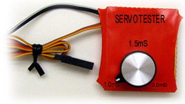
If someone designs an ebike throttle to replace the servo tester it could be designed to:

In other words it could have all of the electrical features we want but be designed to be controlled by a mechanical throttle.
 
Hi Mitch,

Geoff did a reasonable pot box for a mechanical throttle, just looking for the thread.
ahhh here we are ...... http://endless-sphere.com/forums/viewtopic.php?f=6&t=2522&start=0&st=0&sk=t&sd=a
what type are the regular throttles from ebikes.ca - hall? resistitive?

Cheers,

D
 
Agreed Miles, just thought i'd post it for Mitch, the throttles i've had have been low quality but work perfectly, i think it was the throttles with the LED indicator that used to short in the rain on WOT :shock: but personally i've never had a problem.
BTW Merry Christmas Miles :)

Cheers,

D
 
Yes, Merry Christmas. :D

Now that's that's over, I can get back to designing a throttle interface.

I just want to make sure I have the RC stuff right first.

I want a pulse train with 20msec between pulses and a pulse width of 1msec for zero throttle and 2msec for full throttle. Right?

Throttle signal from a standard hall bike throttle is 1v at zero throttle and 4v at full throttle with a 5v supply. For a pot throttle, the signal will go from 0 to 5v. Since these numbers tend to vary a bit, it seems there will need to be a zero adjustment to compensate for variations.

Don't most RC controllers have a zero adjustment? Does the interface need one?
Do most RC controllers have a span adjustment as well? Does the interface need one?

Most everything else I have figured out.
I don't think an adjustable ramp up is needed as long as it has some ramp and the current is limited. If the current limit is set lower, the ramp up will take longer just due to inertia.
I think current limiting is a must, and it's not hard to make it adjustable. For simplicity, I'm assuming battery current limiting, but if I do it right, it should also work on the motor side if installed there. With proper current limiting, you can make the mechanical components nearly bulletproof (at least with respect to operator input).

What's the highest voltage the BEC should be good for? (stupid question on this forum :wink: )
In other words, what's the highest voltage RC controller in the world?
 
fechter said:
Yes, Merry Christmas. :D

Now that's that's over, I can get back to designing a throttle interface.

I just want to make sure I have the RC stuff right first.

I want a pulse train with 20msec between pulses and a pulse width of 1msec for zero throttle and 2msec for full throttle. Right?

Correct.

fechter said:
Throttle signal from a standard hall bike throttle is 1v at zero throttle and 4v at full throttle with a 5v supply. For a pot throttle, the signal will go from 0 to 5v. Since these numbers tend to vary a bit, it seems there will need to be a zero adjustment to compensate for variations.

Don't most RC controllers have a zero adjustment? Does the interface need one?

Yes, most ESCshave a calibration function. Usually, you have to turn on the system, with the throttle stick maxed out, and then return it to zero. Also, some transmitters (Futaba...) reverse the throttle signal, but I don't think this is something that throttle "widget" needs to worry about.

fechter said:
Do most RC controllers have a span adjustment as well? Does the interface need one?

No, I don't think this is needed. This is mainly a servo-related function.

fechter said:
Most everything else I have figured out.
I don't think an adjustable ramp up is needed as long as it has some ramp and the current is limited. If the current limit is set lower, the ramp up will take longer just due to inertia.

I agree. The adjustable ramp was really added for use with helicopters. Without it, high power setups would strip the main gear. With a bike, the ramp should still be there, but it doesn't need to be adjustable.

fechter said:
I think current limiting is a must, and it's not hard to make it adjustable. For simplicity, I'm assuming battery current limiting, but if I do it right, it should also work on the motor side if installed there. With proper current limiting, you can make the mechanical components nearly bulletproof (at least with respect to operator input).

I think battery current limiting is fine.

fechter said:
What's the highest voltage the BEC should be good for? (stupid question on this forum :wink: )
In other words, what's the highest voltage RC controller in the world?

The highest one right now is probably the Kontronik PowerJazz, which is good for 63V. There is a new Scorpion line of SHV controllers (more info here...) that I'm not sure are available yet, but they are supposed to be able to handle 16s LiPos, or about 68V. I do think that there will eventually be 100V controllers, but I think if you did it to be able to handle a typical 24s LiFePO4-based 72V setup, this would pretty much handle 99% of the cases.

-- Gary
 
fechter said:
Most everything else I have figured out.

So what shunt wire did you find? Share your sources, please! I could do well with shunt wire that has a low temperature coefficient.
 
I decided to go with the Allegro hall current sensor. It's only about $5. They have many advantages, like being isolated, have a high output, and are pre-calibrated within a reasonable accuracy.

I've almost finished the design, but need to test a few things on a breadboad first to nail down some component values. I don't trust all the calculations based on the formulas given in the datasheets.
 
My design is using a hall effect throttle as input to an Arduino. In the Arduino, I have implemented a PID controller. For now there are three modes of throttle operation. 1. Standard throttle mode - Acts as a normal throttle with no current limiting. 2. Current limited throttle - I can set the max current and the throttle is limited so that it can not ask for more then the max current setting. The PID controller keeps the current under control. 3. Constant amps mode - You use the throttle to get to the desired current and then flip a switch to capture the current setting. The PID controller keeps you at this current level. The throttle is also limited in this mode so that you can not ask for more the the max current setting.

I am using the +-150 amp version of the Allegro chip in my design. When I have no current through the chip the counts in the A/D are a few short of 512 counts, so I have added some code to handle the issue. If I am doing the math correctly, I only have a bout 2.7 A/D counts per amp. More resolution would be nice. I think I may throw in a circuit to change the 2.5 - 5 V (0-150A) output to 0-5V for more resolution at the A/D.

I had original turned to my buddy for help on this because he has been playing with micro controllers for a long time. When he showed me the Arduino, I was happily surprised at how easy it is to develop on this platform. I have done some programming in the past and I have had no problem getting up to speed. My electronic skills are a little weak, so I will be going back to my buddy for assistance in this area.

So far my results have been good. The PID is controlling things to within about .5 amps of setpoint. With more resolution, I am expecting this to improve. I am still waiting for dry weather to do more testing.

Bubba
 
If you are going the shunt route for current monitoring, this looks good to me. Is there a problem I am missing with this method?

dirty_d wrote: a mcu design would actually be simpler than that. i wouldnt mind helping out with the code if one of you tries to build one. as for shunts, you can get SMT chip resistors on digikey for about 1.50 each, im using two 2W 0.0005R in parallel, so .25 millivolts per amp, 25mV at 100A and 2.5W. id use an op-amp to amplify the voltage across the resistors to 2V or so then feed it to the adc.

fechter wrote:I think current limiting is a must, and it's not hard to make it adjustable. For simplicity, I'm assuming battery current limiting, but if I do it right, it should also work on the motor side if installed there. With proper current limiting, you can make the mechanical components nearly bulletproof (at least with respect to operator input).

I think that current limiting has to be done with the throttle pulse to the esc. From my readings, if you put a current limiting circuit between the battery and the esc it could lead to a blown esc. The CC folks told me to remove the fuse I had between the battery and the esc or it might cause the esc to blow if the fuse went. Take this info with a grain of salt, as I am no electronics expert.

Bubba
 
Funny you guys are talking about this stuff, I was spending the day thinking about how to build a "fixed" armature current limiting circuit that didn't need a separate power supply. The design that Fechter invented worked... sort of... because the voltage sag caused by the circuit tended to mess everything up. So I'm looking to build "Version 2.0" of the idea.

What I'm thinking is to use a voltage regulator and take one of my 24 volt NiCad tubes and run some small wires to the ACL circuit that will run independently. (so I won't drain off the controller supplied current) These wires then go through the voltage regulator and you get a steady 5 volt source to power the current sensor. The voltage regulators can drop down the excess voltage (24V+) if you get the right type. You don't need more than about 50mA.

Good News!

620-CB-5.jpg


http://digikey.com/scripts/DkSearch/dksus.dll?Detail&name=620-1112-ND

These new ones they have in stock are 60mV/A compared to the older ones with 40mV/A.(or the 20mV/A I got with the 100 Amp type)

So this is 50% more accurate than before! :)

Lastly... for those that might be thinking about Armature side limiting rather than Battery side here's a thought:

Take a current sensor and attach it to just one of the three brushless motor wires, then when you do the comparison with the comparator you just scale down the current by three.

So a 60 amp current limit (at the motor) means that you set up your circuit to read one of the wires and limit based on 20 amps. It should be no more difficult than brushed motor limiting...

Just divide by three. :wink:

Armature Current Limiting would also reduce the stresses on your drivetrain while at the same time reducing heat.

----------------------------

http://digikey.com/scripts/DkSearch/dksus.dll?Detail&name=620-1193-1-ND

This one also might work for me because I'm going to run at a maximum of about 30 amps. It has an exceptionally good performance rating:

133mV/A 8)

...and only $2.90.
 
if you do decide to get a servo tester i see them on ebay for less than$20 shipped

http://search.ebay.com/servo-tester_W0QQcatrefZC5QQfasiZ1QQfbfmtZ1QQfclZ3QQfromZR7QQfrppZ200QQfsooZ1QQfsopZ34QQsabfmtsZ2QQsacatZQ2d1QQsascsZ2QQsbrbinZtQQsbrsrtZdQQsofindtypeZ0

swbluto said:
I was just messing around with my microchip and I've successfully converted a voltage-signal from a regular crystalyte throttle(or any regular voltage-based throttle) into a servo-train pulse that outrunner controllers run off of so, basically, that means I can directly connect a crystalyte throttle to the RC controller using this signal converter! Which means less money out of my pocket for a servo tester and I don't have to deal with a servo tester's weirdness for e-bike/e-scooter/e-etc. throttle use.

If there's enough interest, I may consider developing it into a product and offering it to the community. What do y'all think?

Right now, I'm planning on adding throttle limiting abilities for current-control and also an appropriate throttle ramp so that I won't be thrown off my scooter.
 
dontsendbubbamail said:
I think that current limiting has to be done with the throttle pulse to the esc. From my readings, if you put a current limiting circuit between the battery and the esc it could lead to a blown esc. The CC folks told me to remove the fuse I had between the battery and the esc or it might cause the esc to blow if the fuse went. Take this info with a grain of salt, as I am no electronics expert.

Bubba

Yes, the limiting circuit works by decreasing the throttle signal when the limit is reached.

Based on experience, the response speed of the feedback loop is critical. If the response is too fast, the system will go into oscillation. If the response is too slow, there could be a lot of overshoot in the current. If you're designing code, you want to have an adjustable parameter for response speed. In my analog circuit, there is a slew rate limiter on the feedback signal going to the throttle. The optimum response depends somewhat on the particular controller model and mechanical configuration of the drive (inertia).

I don't think having no fuse is a good idea. I'd rather have a blown controller than set my bike on fire.

Safe, when using motor current limiting on a brushless motor, you have to deal with an AC signal on the current. The current in each motor phase will be reversed half the time. This is not a big problem, but has to be designed for.
 
SPEEDY_BL_verpackt.jpg

fechter said:
Safe, when using motor current limiting on a brushless motor, you have to deal with an AC signal on the current. The current in each motor phase will be reversed half the time. This is not a big problem, but has to be designed for.
Square Wave?

Is it an A/C wave or is it really a DC square (trapezoidal) wave?

Check out this website:

http://www.aerodesign.de/peter/2001/LRK350/SPEEDY-BL_eng.html

MOSFET%20Gates.gif


Teillast_Gates_zoom.gif


...so in these images it appears that the DC current is simply "chopped" in the same way that a PWM controller might work.

A brushless controllers current more closely resembles a PWM current than an A/C current. (if I'm correct on this) But the PWM is both chopped three ways for the motor and also can be chopped within the larger signal for each of the three. The chopping is much more complicated, but it's still PWM.

:?: What is the truth?

Peter_bei_der_Arbeit..jpg


The actual motor wires see this:
Motor-3-phasen-zoom.gif

The square waves sent to the MOSFETS translate into a lag time because the gates don't open immediately, but the idea is the same, that the power is DC and ALWAYS positive. But each wire gets just one third of the current in total.
 
safe said:
The square waves sent to the MOSFETS translate into a lag time because the gates don't open immediately, but the idea is the same, that the power is DC and ALWAYS positive. But each wire gets just one third of the current in total.

The voltage is always positive with respect to battery negative, but the current in the phase wires will reverse half the time (measure it sometime).

The PWM introduces the same kind of problem in both brushed and brushless systems and needs to be filtered out of the current sensing circuit.
 
fechter said:
The voltage is always positive with respect to battery negative, but the current in the phase wires will reverse half the time (measure it sometime).
That makes no sense... :?

Maybe because of the inductance of the wires you might get some oscillations in the rate of current flow (in fact you have to see the current oscillate somewhat) but the current always will flow FORWARD.

It has to...

Otherwise you would have some current flowing backwards through the MOSFETS. (which might take place, but should be a small value) Where does this current flow "to" if it's going backwards? (keep in mind that all we are dealing with is a MOSFET that is either open or closed... the controller does not itself create an A/C current)

How do you know that current flows backwards?

The speed of these PWM pulses is very high, so I just don't know what gives you the "insider knowledge" about the current flow.

Do you have special measurement tools?

Are you somehow getting the Back EMF mixed into this reading?

Inductance can play some weird tricks (so I'm open to the idea that something bizarre is happening) but I'm not satisfied in understanding the idea of reverse current flow yet.
 
For one, I've actually measured it on a motor.

This isn't rocket science here. Each phase wire gets connected to either bat+ or bat- by the FETs at various parts of the cycle. When the phase wire is connected to the + side, the current will be going from the battery into the phase wire. When the phase wire is connected to the neg. side, current is going from the wire into the battery. The current reverses.
 
fechter said:
When the phase wire is connected to the neg. side, current is going from the wire into the battery. The current reverses.

Safe, I think when this wire is connected to the battery's negative terminal through the mosfet, there's another phase linked to this given phase that's connected to the battery's + terminal. So the given phase that's connected to the batt's negative terminal is "sending current back" to the battery's negative, but there's a corresponding phase wire connected to the positive battery terminal that's drawing current from the battery's positive terminal. So the battery is always flowing from positive to negative, it's that a given phase wire alternates between the battery's + and - terminals.(And I believe it also is "disconnected" a third of the time, too. Or, rather, the circuit isn't closed even though it might be connected to one of the battery's terminals. I don't know about that, though.)

And, yes, there are bidirectional mosfets that'll conduct roughly equally well in both directions. I think the common place "N-type enhancement mode MOSfets" can do this.
 
This is probably the best explanation I've found:

http://en.wikipedia.org/wiki/Brushless_DC_electric_motor

"Although BLDC motors are practically identical to permanent magnet AC motors, the controller implementation is what makes them DC. While AC motors feed sinusoidal current simultaneously to each of the legs (with an equal phase distribution), DC controllers only approximate this by feeding full positive and negative current to two of the legs at a time. The major advantage of this is that both the logic controllers and battery power sources operate on DC, such as in computers and electric cars.

Vector drives are DC controllers that take the extra step of converting back to AC for the motor. The DC-to-AC conversion circuitry is usually expensive and less efficient, but they have the advantage of being able to run smoothly at very low speeds or completely stop in a position not directly aligned with a pole. Motors used with a vector drive are typically called AC motors."


So it's true...

"DC controllers only approximate this by feeding full positive and negative current to two of the legs at a time."

Which means that a brushless motor has a sort of "push-pull" going on rather than just the forward direction pulses of current. This means that it's even more complicated to do armature current limiting, which means control is difficult to implement.

Hmmmmm.... expensive, hard to control, hard to geardown...

It's a difficult task to get this to work well... :?

However...

Ordinary Battery Side Current limiting would be the same... just place the sensor on the battery wires before the controller and you can limit that way. So it's not so bad. :)
 
Tachometer?

Rather than approaching the idea of Armature Current Limiting on Brushless Motors from the true "current" side. (measuring the actual current) The far easier way to do this is to use a tachometer and set up some circuit that reads the tachometer signal (which increases linearly) and match the "known" throttle ramp rate (calculated) verses the actual.

We know what the duty cycle "should" be for a maximum for any given rpm and so we can trim down the throttle accordingly.

There is a one-to-one relationship of "known" duty cycle and rpm for any Armature Current Limiting implementation.

The tachometer approach has the advantage that it does not matter if it's a brushed or a brushless motor since they will behave the same way... :)

This might be a nice little project:

"The Universal Armature Current Limiting Circuit"

Alternatively...

You could figure out the rpm based on the back EMF signal. Since there are three of the back EMF signals per rpm you could use that as your tachometer to arrive at the "approved" throttle setting for any given rpm.

The nice thing about this type of limiting is that it still allows full top end power, but lessons any problems of overheating and softens the strain on the transmission. Less worries about ripping your chain or hub apart.
 
Don't forget the safety brake circuit along with the regular e-bike throttle if you want it to be legal.
 
Back
Top