What about CA3-WP and MFSwitch and Aux input ?

Pegazus

100 mW
Joined
May 18, 2019
Messages
45
Hi everyone,

I have a question about the new CA3-WP with MFSwitch.

https://ebikes.ca/shop/electric-bicycle-parts/cycle-analysts/ca3-wp-and-mfswitch.html

I can't find any wiring diagram for this new cycle analyst, especially about the aux input.

So here are my interrogations:
- What about the regular aux input cable? Is it still there? If yes, is it connected to the same location on the electronic board?
- What about the possibility with the MFswitch version to add a 3 position switch? A potentiometer?

Thank you for your support :)
 
Pegazus said:
Hi everyone,

I have a question about the new CA3-WP with MFSwitch.

https://ebikes.ca/shop/electric-bicycle-parts/cycle-analysts/ca3-wp-and-mfswitch.html

I can't find any wiring diagram for this new cycle analyst, especially about the aux input.

So here are my interrogations:
- What about the regular aux input cable? Is it still there? If yes, is it connected to the same location on the electronic board?
- What about the possibility with the MFswitch version to add a 3 position switch? A potentiometer?

Thank you for your support :)
Interesting. The link on the product page to the manual is the same as for a standard v3.1 CA, which might imply it has the same connectors, and the pic appears to show the same bundle of connectors in addition to the Higo.

The interesting thing that hopefully you can report back on, is that the Higo includes a Key Sw pin, and the MFS has a power button, so it would be interesting to see if you can actually power off both the controller and CA via the switch.
 
On my side I’m really surprised to find so little information about the wiring diagram and all the description of this new feature.

It seems that not so many people bought it yet.
 
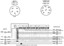
Here's a sketch of my ca3.1-wp-mfs. Mainly opened it up to see where the buttons connect to internally, also to estimate a current rating for the power switch. It seems to use an active switch built in to the housing. The up/down arrow keys connect to 2 different resistors to ground. Working ok so far with my no-name ebay 120v 18 fet controller.
 

Attachments

  • CA31_wp_mfs.png
    CA31_wp_mfs.png
    50.3 KB · Views: 363
socrace said:
Here's a sketch of my ca3.1-wp-mfs. Mainly opened it up to see where the buttons connect to internally, also to estimate a current rating for the power switch. It seems to use an active switch built in to the housing. The up/down arrow keys connect to 2 different resistors to ground. Working ok so far with my no-name ebay 120v 18 fet controller.

Old thread but I hooked up the MF switch to an arduino today and this is what I found:
-The green wire is from the Up/Down switch and I wired it into an analog input:
On startup, the signal on the green wire start gradually incrementing from 0 to 1023
If the 'UP' button is pressed, the signal falls to zero; when released, the signal starts incrementing again
When the 'DOWN' button is pressed, the signals drops quickly but not to zero.
-The blue wire is the Mode button and was wired to a digital input (with a arduino pullup resister enabled)
The input is "1" until pressed and then goes to "0"
Returns to "1" when the button is released.
-The yellow wire is for "On/Off".
I couldn't get it's digital input to change state no matter what i did.
 
Again, old topic but since CA3-WPx is on the market for some time hope that somebody can answer.

Does MFSwitch 5 pin plug to CA3-WPx replace the JST-MF 3-pin analog input connector that could be used with Auxilliary Potentiometer ? Or is MFSwitch 5 pin plug additional and JST-MF 3-pin analog input is still available for CA3-WPx?
 
Back
Top