NeilP
1 GW
Today I was given a outdoor halogen lamp style lamp, but it had either been converted to an LED board or bought like I had it
Like the one in the image below but with only 48 LED's in it.
I wonder if it had been converted, as it was a mess inside, I certainly hope Sealey did not produce them like I found it
RThe back of the board was marked up as 12 volt, but half of the tracks on the back had been cut and it had been re wired so there was 12 LED 's in series instead of the original design which put just 4 in series.
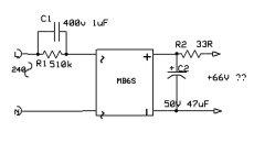
Inside was s small 1 inch by 1 inch circuit board, with a tiny rectifier in a 4 pin package about 5mm x 5mm. The whole lot wrapped in black insulating tape!!

Under no load I measured 66 volt on the output, so that makes 5.5 volts per LED as it was wired.
Now the original wiring put 12 volts across 4 LED's
That gave 12 strings of 4 in parallel.
When I put 12 volt across it all the LED's lit up, and the board took 0.2 amps
I never ran it up at the 66 volts from rectifier board, so did not see it working at that voltage, and seeing the shoddy way it was built, I did not fancy it..just in case it was too much.
So anyone know what I could likely run these LED's at per LED? is the 5 volt safe or is that likely to cook them in short time...Or maybe measuring the voltage of this little rectifier board unloaded was not the correct thing to do, under load it probably gave a voltage drop

Like the one in the image below but with only 48 LED's in it.
I wonder if it had been converted, as it was a mess inside, I certainly hope Sealey did not produce them like I found it
RThe back of the board was marked up as 12 volt, but half of the tracks on the back had been cut and it had been re wired so there was 12 LED 's in series instead of the original design which put just 4 in series.
Inside was s small 1 inch by 1 inch circuit board, with a tiny rectifier in a 4 pin package about 5mm x 5mm. The whole lot wrapped in black insulating tape!!

Under no load I measured 66 volt on the output, so that makes 5.5 volts per LED as it was wired.
Now the original wiring put 12 volts across 4 LED's
That gave 12 strings of 4 in parallel.
When I put 12 volt across it all the LED's lit up, and the board took 0.2 amps
I never ran it up at the 66 volts from rectifier board, so did not see it working at that voltage, and seeing the shoddy way it was built, I did not fancy it..just in case it was too much.
So anyone know what I could likely run these LED's at per LED? is the 5 volt safe or is that likely to cook them in short time...Or maybe measuring the voltage of this little rectifier board unloaded was not the correct thing to do, under load it probably gave a voltage drop


