Wheelchair with Handcycle

I use Anderson PowerPoles for large wire connections. I use Posilock connectors if I am trying out different connections like for Hall/phase on a new motor and controller. They can be permanent but make it easy to switch wires to get correct combinations. JST work fine for controller connections and throttle.
otherDoc
 
With the 46 Calb 200ah lithium batteries that I have in my Toyota Yaris, I never go below 10-15% or above 90-95%. I charge off my solar panels @ 80V. Anyways, I do not use a BMS, instead use a 1/2 pack monitor (will soon go to a 1/4 pack monitor) and can see if one of the voltages is lower in one side than the other then there is a weak cell. But mostly charge when I get to 40%.

But I am using Turnigy Lithium-Polymer (the 2x 36v 8.3ah) battery packs with BMS I inherited and wondering if they are more tricky? I hear can be dangerous if not used right.

Experiences with LI-PO anyone?

francis
 
I like those 9pin Q100/Q128 motor wires. I splice directly to the controller once happy with wire runs.

Primarily use APP’s (Anderson power poles) with the crimper for main power connections but I also use a mixture of other stuff sourced from RC Hobby suppliers.

4mm gold bullets always seem to come in handy. As well as Futaba servo connectors. I use ‘em for motor Hall signal connections (they fit through axle hardware) also throttle, brake, lighting, etc., all around connections.

I use more of a custom approach with my 2kW DD (direct drive) and that’s where I go with the Futaba servo connectors and 4mm gold bullets for phase power wires.

JST contacts come in handy when fixing RC Lipo balance wires and I use the same crimp tool for them that I got for Futaba contacts.

Wire - lotsa 12ga silicone stuff in my stash. Various shrink-wrap tubing too.
 
Aloha, I was going to buy a cheap spare controller from ebay to experiment with.

Can the Q100h take 60v as long as I keep the current down

OR

Can I get a 60v controller and even though it may be rated at 25amps, as long as I do not burden the motor with full throttle or extended
hill climbs, will I be OK?

AND

Is not VxA=Watts? then why do I see ads on ebay for controllers 48v with 25 amps equaling 350 watts?


thanks
francis
 
yes, yes, and;
https://endless-sphere.com/forums/viewtopic.php?f=2&t=74403
 
dilkes said:
I just happened to be reading this article https://www.electricbike.com/ebike-connectors/ from the Luna Cycles website. You might find it useful.

In spite of the author's knocking the Anderson Powerpoles, that's what I use.

In their eagerness to knock APP’s the author conveniently ignores APP’s ease of series/parallel configurations. Many users get down on APP's because they're unable to crimp and assemble properly. Some people can't sharpen a pencil, it's not the pencil's fault...

And let’s not overlook the fact that all of the supposed “approved” connector alternatives require soldering which when used for main power and repeated connecting/disconnecting often leads to a broken wire where solder has wicked up into the wire strands. No fun on a dark road somewhere in BFE…

And they recommend XT60’s? Is that supposed to be a joke? I use ‘em for my RC aircraft but they’re way down on my list for eBike connector. Majority of the time they almost fit too tight and then you start messing with the “fit” and create more problems.

Oh well, I’ve only ridden this shit daily for 10 years nearing 50k hard NYC miles - what do I know?
 
Just recieved 5 pairs of these from aliexpress under 8USD, free shipping.
Planning to use them for low-current lines like hall sensors, throttle/3-spd etc.
Available in 2, 3, 4 or 5pin versions, standard with 20cm (approx 8") pigtails but length can be customized. Lots of Aliexpress vendors.
The wire is 5mm dia and somewhat stiff which may or may not be a good thing.
Bare connectors with solder terminals also exist, but they tend to be more expensive.
 
Look up lipo fires.
Do read up on the many threads here on E.S. before starting.
Lipo fire 15 houses down the street and one 3 blocks from my house in 3 months. Lipo fire yes.
 
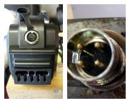
Does anyone know what this connector is called? or where the male (charger) side can be sourced?
Juggernaut.jpg
You can see there are 4 pins, but only 2 are actually in use. The 4 pins are in a perfect square.
 
aloha, all. can you make out if this is a brush or brushless controller? IF B/L does it have Hall effect?

http://www.ebay.com/itm/1000W-48-V-DC-Speed-Controller-Control-Box-Scooter-Electric-Motor-Go-Kart-XQ-/131660768311?ssPageName=ADME:X:RTQ:US:1123

thanks
francis
 
It would appear to be for a brushed motor.
 
I've taken to summing up RC lipo in one sentence. Never store them or charge them in a place you would not build a fire.

It's not that likely,,, I've been running lipo for years now, with no fires. Follow basic rules, bla bla bla. get rid of packs ruined by dings, bad puffs, overcharged, overdischarged, etc.

But it's the potential to burn your house down, that makes you need to be careful. Those cells are notoriously poorly quality controlled. So just like you wouldn't store a gallon of gas inside your apartment,,,,
 
Aloha and thanks for all the advice, folks. Learning stuff day by day.
I will make a quick-release for my battery box so I can jettison it if need be.
I am Starting out with some lead 12v series 48-60v 9ah that are surprisingly durable. (had them 9 years and they still take a 13.2v charge)
They only have 1/4 inch spade connectors, so I may have to go 60v to keep the amperage down.

I will play with them at varying voltages and my q100h motor and 16" rim with different controllers, 48v or 60 or 72 v to see what I like.
Cheap controllers with one voltage setting @$25.00 range seem to be the way to go, as I can burn one out and be OK rather than getting a variable
voltage one 36-72v @ $125.00.

Anyways on with the fun/show.

francis
 
Aloha, all. Can someone explain the following chart where 48v is constant, and when amps are increased, the RPM goes down. Seems like it should be more amps, more rpm?
thanks
Francis
http://www.leafmotor.com/electric-bike-motors/phbl-hub-motor.pdf
 
Without seeing any other data, I make the assumption they are talking about what it takes to get a motor spinning and keep it spinning.

It takes more amps to get it moving then to sustain the movement.

:D
 
Peak efficiency is reached when the no-load speed is dragged down from 451 RPM to 400, 88% and 477W of load. The output power column is the load that causes the RPMS to drop while the amps increase.
 
Ok, I am still not understanding.

According to the chart, the more amps I apply to the motor, the slower the rpm becomes? ie at 1.8 amps I get 451 rpm but at 29.2 amps I get 174 rpm. the bike is slowing down.

I don't get it

francis
 
The way the test works is they spin the motor up on the dyno with virtually no load, ie highest rpm. Then test machine starts applying load requiring torque from the motor with measurements as that load increases. The controller delivers current up to it's set limit (just under 30 amps in this case) as torque is requested from the motor, which in the linked test peaked at 45 Nm of torque.
 
spdas said:
Ok, I am still not understanding.

According to the chart, the more amps I apply to the motor, the slower the rpm becomes? ie at 1.8 amps I get 451 rpm but at 29.2 amps I get 174 rpm. the bike is slowing down.

I don't get it

francis

The charts show the motor behavior at different conditions.

For the above example, suppose the motor is spinning at 174 rpm, if you apply full throttle the motor will draw 29.2 Amps which will generate 44930 mN.m of torque.
The torque will accelerate the motor until reaches 451 RPM at which point it will draw 1.8 amps and generate only 450 mN.m which will not be enough to accelerate any more.

The way to look at it is not "the more amps you apply, the slower the rpm becomes", rather, "the slower the motor is spinning, the more Amps it can pull".

Avner
 
I don't know the proper term, but its a loading chart, showing resulting amps and efficiency at various RPMs.

In this example, you don't apply amps, the controller adds amps in response to a slowly increasing load. The top of the chart has the max RPMs, and as load is slowly and evenly being applied the RPMs steadily go down. The amps go up, and the efficiency curve goes up first and then down.

Max efficiency of 85% is at 11A and 400-RPM

400-RPM in a 26-inch tire is around 31-MPH (50 km/h)
 
Thanks for the help. I will try wrap my mind around the explanation.

francis
 
Here's another way to look at it... you're out riding, giving it full throttle, and its slightly down hill, and your wheel RPM goes up to 450ish. You will then be drawing 1.8 amps. Then you start going up hill. As the wheel starts slowing down, and you keep the throttle at max, more amps start flowing thru the windings as the RPM drops and the back EMF goes down. As the hill gets steeper, you hit a point where wide open throttle only produces 174 RPM because of the load of the hill, and it's taking almost 30 amps to keep it at that RPM as you climb. So its not that the higher amps are causing the slow down, its that a load on the system that's forcing the motor to lower RPMs gets higher amps flowing.
 
Voltron said:
Here's another way to look at it... you're out riding, giving it full throttle, and its slightly down hill, and your wheel RPM goes up to 450ish. You will then be drawing 1.8 amps. Then you start going up hill. As the wheel starts slowing down, and you keep the throttle at max, more amps start flowing thru the windings as the RPM drops and the back EMF goes down. As the hill gets steeper, you hit a point where wide open throttle only produces 174 RPM because of the load of the hill, and it's taking almost 30 amps to keep it at that RPM as you climb. So its not that the higher amps are causing the slow down, its that a load on the system that's forcing the motor to lower RPMs gets higher amps flowing.

To me the chart would be meaningful it they had another column showing 1 pounds of load requiring x amps, and producing y rpm,, then 2 pounds load requiring 3x amps, 4y rpm etc.
thanks
francis
 
That would be nice... but do you understand now that the higher amps aren't CAUSING the lower RPMs, but are a result of a load forcing the RPMs lower?
 
Back
Top