Wheelchair with Handcycle

Aloha, I can bump it up to 59v to see what happens. Here is more of a description of what is happening.

During acceleration, I can see 500-600 or so watts. Then as the speed increases, the watts drop and hover around 350w and get to 11mph. The motor lurches and "hunts" back and forth 11-12 mph. Wanting to increase and cutting back...Weird.

francis
 
spdas said:
I can bump it up to 59v to see what happens.

You could....but no guarantee that you won't burn up your controller....

Have you opened that controller to check the voltages of the capacitors?

:D
 
Aloha, the large cap is 63v. I see some small caps on the board @50v. I assume the determining voltage would be the 63v as I could not see the controller rated at 36/48v with only 50v limit.

Also do controllers that are multi voltage, such as my 36/48 "auto-switch" internally to a hi and low range for 36 and another for 48v? ie, If I have a 48v battery hooked up, will the controller cut off at say 42v, even though @42v it is still above the 36v?
Does the controller consider voltage as well as taking into consideration amperage/sag?

Inquiring minds wanna know.

thanks
Francis
 
Aloha, I got my old rig working. Has a 36v motor/controller combo and travels 14mph. I made a series 4 x 4s @5000mah lipos 59.2v and now runs 21mph with lots more midrange. The batteries came out to 62v when after I used my balance board and did not fry the very cheap original controller, so I assume we have 63v caps.

But here is the problem. After I depleted the batteries to 3v I charged the batteries with a 60v lipo charger (the large black plastic generic ones that are stuffed with anywhere from 24v-72v charge boards) but it did not shut or taper off but I caught it "just in time" as I as monitoring them with a cell-log, but the pack is at 68v (4.25 PER CELL) and I do not want to push my luck on hooking it up to the cheapo controller, so would like to discharge down to 62-63 volts.

1) with lipos where is the top of bulk of the charge energy? 3.9v ? 3.85v? 4.0v? ie where going up to 4.25v may only account for 5% of the battery amperage.
2) how can I discharge? plug into a heat gun or heater? How about running my second pack of 4 x 4s 5000mah lipos to say 58v and hooking up them together parrallel? ... drain the 68v one down into the 58v?

Ideas?

thanks francis
 
1) with lipos where is the top of bulk of the charge energy? 3.9v ? 3.85v? 4.0v?
If I understand the question it really depends on the condition of your cells....Type of chemersty + usage + age ='s current contition.....or something like that. :lol:

Anyway, with new cells, it is really around it't rating. So if your cells are new, then the top useful watts are really around 3.7 to 3.4 volts..... give or take. Look around for a lipo discharge chart for your cells.

2) how can I discharge? plug into a heat gun or heater?

Anything that can give you a safe resistive load.... aka "dump load resistor" or "bleeder resistor." An incandescent light bulb could work. Maybe a dump-load resistor from a wind turbine. Resistors can get hot so be careful.

How about running my second pack of 4 x 4s 5000mah lipos to say 58v and hooking up them together parrallel? ... drain the 68v one down into the 58v?
Ideas?

https://endless-sphere.com/forums/viewtopic.php?p=266847#p266847

:D

Edit: Your charger probably has a bleed resistor built into it. Un-plug your charger and plug your battery into your charger. Leave it for an hour or so and see if the voltage in your battery has dropped.
 
Aloha,

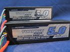
They are Lithium Polymer. see sample pix. 5.0 ah 4s, 14.8 hard case in series to get 59.2v
5.0ah.jpg
I drained them down by hooking up 3 packs in series to get 44.4v and ran it a bunch. I am very surprised as I started out with 4.25 per cell and after 2 miles I am still at 4.15v. (they sure do NOT drop off as fast as Lithium-fe or Lithium-ion that I am used to.) I am going to run another 2-3 miles and see how far they drop in voltage, if around 3.9 or so I will put the 3 packs with the 4.25v hi one on the balancer.

francis
 
Aloha, if your controller has 63v caps.-- is there any wiggle room? such as "can go up to 66v?"

Anyone had experience with the frying point?

francis
 
spdas said:
Aloha, if your controller has 63v caps.-- is there any wiggle room? such as "can go up to 66v?" Anyone had experience with the frying point......

Not me...I just respect the manufactures ratings. I suppose one could pull a cap from a controller to apply an over-voltage test, it would save destroying the whole controller. I have a bench power supply for tests like that. One cap vs the power supply...... :lol:

:D
 
Aloha, All. I am still having trouble with this controller limiting to 20kph and I got a response from the seller:...............

"speed signal wire is to display the speed information and you could connect it to the three-speed third of the car to adjust the speed"

What does that mean?

here is el cheapo controller.

http://www.ebay.com/itm/371239291127?_trksid=p2057872.m2749.l2649&ssPageName=STRK%3AMEBIDX%3AIT

francis
 
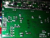
Aloha, all. I opened up the controller and see a pad with Lo, HI, Tx with nothing connected. (see photo) can I attach wires to here and do you think this is the speed controller?
board crop.jpg
thanks
francis
 
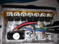
Aloha all, I messed up my tiny controller finally and wondering how easy it would be to fix. It turns on, LCD display comes on, but the LED inside the controller blinks as soon as the throttle is pressed. I have been running this controller (with 50v caps) at 64 volts for 2 weeks with no problems until i started playing around and going up curbs and then it stopped!

Nothing seems to be burned or there is no burned smell, so what do you think would be the first thing to let go? Photo below. I would like to fix it because it is so compact (60x90mm) and has the LCD display and very clean compact wiring.

thanks
francis


controlerSherpa.jpg
 
Whats happening here?

I hooked up a 800w 64volt controller and tried all the green/blue/yellow combo's. but have this issue. (I also tried a different throttle)

1) using 1/16 throttle and getting to 4-5 mph, if I give it more than 1/8 to 1/4 throttle, the motor cuts out and I have to go to 0 throttle and feather it to get to 1/4 throttle

2) then getting going in increments as above, I get to 1/4 throttle and 10mph I try just about 1/2 throttle and the motor cuts out and i have to back off.

3) I am gaining speed all the time and able to use larger throttle openings. I do this several more times and finally at 1/2 throttle I can "floor it" and go to full throttle and 25mph+ with no motor stopping.

What is happening? and where do I look for the solution? Halls?

BTW using the learning wire the motor spins and then cuts off.

thanks
Francis
 
Never over charge your battery. Never. 4.2v per cell. Don't discharge below 3.4 volt. You are playing with lipo, so be careful. Not a toy monitor and make sure they are balance. Always. Important.
Do you have a cellog to check ?
 
Are your batteries sagging past low voltage cutoff while under load?

What does your watt meter say?

+1 on being Veeeeeeeery careful with lipo.

:D
 
Aloha, y'all I have the packs balanced and measured with a cellog.

The cells are at 3.8v right now, so will charge them up and see if that helps.

The voltage starts at 60.8 and will cut off as described even when it "sags to" 60.5v, so low voltage does not seem to be the problem. At full throttle and full speed the sag is to 58.5v

I don't have an ammeter or my CA hooked up on this unit so could not test the Watt drain.

And BTW I have a quick-jettison release system to get rid of the battery in case of emergency.

Do hall wire arrangements either work or they don't or can some wire switching work "kinda good" and others really good?

Francis
 
spdas said:
Whats happening here?

I hooked up a 800w 64volt controller and tried all the green/blue/yellow combo's. but have this issue. (I also tried a different throttle)

1) using 1/16 throttle and getting to 4-5 mph, if I give it more than 1/8 to 1/4 throttle, the motor cuts out and I have to go to 0 throttle and feather it to get to 1/4 throttle

2) then getting going in increments as above, I get to 1/4 throttle and 10mph I try just about 1/2 throttle and the motor cuts out and i have to back off.

3) I am gaining speed all the time and able to use larger throttle openings. I do this several more times and finally at 1/2 throttle I can "floor it" and go to full throttle and 25mph+ with no motor stopping.

What is happening? and where do I look for the solution? Halls?

BTW using the learning wire the motor spins and then cuts off.

thanks
Francis

I gave the batteries a full charge to 67v and the throttle still is weird. I found this post by John below:


***** John in CR » Sun Oct 18, 2015 2:26 am
The main culprit causing your jerky throttle response is having the phase current limit set too high along with current ramp up time too short.*******


Do you think this applies and how do I fix it, if it does?
 
spdas said:
I gave the batteries a full charge to 67v and the throttle still is weird. I found this post by John below:

***** John in CR » Sun Oct 18, 2015 2:26 am
The main culprit causing your jerky throttle response is having the phase current limit set too high along with current ramp up time too short.*******

Do you think this applies and how do I fix it, if it does?

Things like "having the phase current limit set too high" are quotes from those who have components like a Cycle Analyst. Something you can set your system up with electronically.

So if you are not running a CA at the moment the the John in CR post probably doesn't apply.

Have you bench tested your throttle? Sometimes the hall sensors in them go bad and are inconsistent in their performance. In the past when my throttles have gone out they cause juddering and eventually stop working.

Also, are you running break levers with cutout buttons in them? If so, are they causing problems?

:D
 
e-beach said:
spdas said:
I gave the batteries a full charge to 67v and the throttle still is weird. I found this post by John below:

***** John in CR » Sun Oct 18, 2015 2:26 am
The main culprit causing your jerky throttle response is having the phase current limit set too high along with current ramp up time too short.*******

Do you think this applies and how do I fix it, if it does?

Things like "having the phase current limit set too high" are quotes from those who have components like a Cycle Analyst. Something you can set your system up with electronically.

So if you are not running a CA at the moment the the John in CR post probably doesn't apply.

Have you bench tested your throttle? Sometimes the hall sensors in them go bad and are inconsistent in their performance. In the past when my throttles have gone out they cause juddering and eventually stop working.

Also, are you running break levers with cutout buttons in them? If so, are they causing problems?

:D

1) I used a CA at first and had the same trouble. Now I run without

2) I tried another throttle and the same performance result

3) nothing connected to the brake levers

Do you think it is still possibly the blue/yellow/green BLUE/YELLOW/GREEN exercise as I could go through it again as I could have missed one. (just hate cutting the wires again!)

thanks, Francis
 
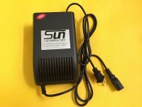
Aloha, I have 16s (59.2) @ 5000mah battery and using the generic 60v charger. (the black box ones you see below) It does not throttle down when charging and will overcharge. I have to use a timer to shut it off manually.
Is there a better charger out there to use?
6vcharge.jpg

thanks
Francis
 
I'm assuming your pack is LiFePo4. What do you mean by it "overcharges"? If you mean it runs longer than it should that could be because it is attempting to balance them at the top end of the charge so the charger would need to keep pumping low current out so the BMS (guaranteed to be a bleeder BMS) can do it's job of equalizing the charge across cells.

If it just will charge infiniately then

1.) The charger voltage cutout voltage or current are set too high
2.) You don't have BMS on your pack or your BMS is not functioning.

There are TONS of charger and charging methods and options out there but to give you any advice we first need to know more about the battery, what type is it, does it have a BMS, capacity, directions for charging as provided by manufacturer, etc.

William
 
Get the real specs from the charger label. That 60V sticker could mean nominal and not max output voltage, in which case the max output voltage could be 67V or higher. It would also help yo know what kund of 16s battery pack you have, with or without a bms.
 
Aloha,

1) no BMS
2) no load voltage on the charger 75.6
3) Lipo 16 cells 5.0 ah
4) It was still charging (the first time I used it) @ 70v so I quickly turned it off and used a balancer to bleed it off to 66v
5) the cells are balanced and I use my cellog to verify
6) not sure if there is a pot inside the charger to adjust voltage?

thanks
francis

I just looked at the back of the charger along with a couple more chargers I have (a 20s and a 24s) and the voltage claimed on the tag are VERY inconsistent and don't make sense.
Some equate to 3.65 v per cell up to others at 4.65v per cell.

But you are right, the 60v on the sticker conflicts with the 20s that is claimed on the tag underneath, so this is the wrong charger...not a 16s.
 
Further Development.

I just did a 10 mile ride and the problem is >

Mostly on startup when the wheel is not turning or turning under 3-5mph ...is where the throttle gives the most trouble.
After 10mph or so the you can use the throttle all over the place and the motor will not cutout.

francis
 
You could look inside for an adjustment pot, but most small chargers like that don't have one. You could wire up a voltage divider with a pot to adjust voltage, or myabe use a single resistor to lower voltage. I'd try 5 ohm 20W to start. This might help.
http://www.gtsparkplugs.com/Dropping_Resistor_Calc.html
 
May I suggest you order a CC/CV charger (the aluminum kind) from any vendor (BMSBattery) or obtain a Meanwell S-150-48 to S-350-48 power supply which operate in CC/CV (may require mods of two resistors, adding a single diode in series with an existing on on the PCB and perhaps a pot) and no matter which way you go order or calibrate it to: 66.4 v No Load?

You said you used a bleeding balancer to drain them from 70v down to 66 and that they are now in balance, providing the cells are of decent quality and IR or impedance matched well enough they should tend to stay in balance (within 20mv) all on their own and by setting the no load charger or power supply output voltage at 66.4 you are going to 4.15v per cell.

I personally use this method with hobbyking turnigy and zippy flight max packs I've assembled (such as a 14S2P for use with a BBS02-48) and bluntly I can't remember the last time I balanced them.

Adding some form of High Voltage cutout and Low Voltage Cutout circuit would be a very good idea too although I don't often follow my own advice on that one since I never use > than 90-93% of the total rated capacity of each pack anyway and my controller is set to cutout at 3.35v per cell in use or 47v.

There are topics in abundance here on modifying meanwell supplies into chargers, altering the voltage adjustment range, etc.

No matter what I would not exceed 300-330w output power so your 5000mah Lipo would receive a 1C charge and be done in roughly an hour using a 300-330w CC/CV charger or modified S-350-48 and if your not in that kind of hurry you can extend the cycle life of the pack by charging at 150 watts (166 watts actually) for a 2.5A Charge Rate but it will take 2 hours to fully charge.

The good news is, no matter what your poision is there are an abundant paths to a safer charge session and a longer lived pack - and chargers in the 150-300w range are available quite cheaply if your not a DIY type.

-William

PS:
I am using a modified S-150-48 right now configured for 58.1v (4.15v per cell) to slow charge a 14S 5000mah RC Lipo Pack at 2.58A charge rate and have managed to mod it so I can adjust it for all the way up to 74.7v for 18S packs.
 
Back
Top