fechter said:
In reading more carefully, it seems the circuit board might do the limiting and the wall wart is just a raw supply. It will need some kind of current limiting to avoid overloading the transformer.
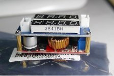
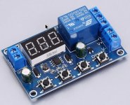
Indeed. The buck converter I have allows you to set the constant voltage and limit the max. current. The extra required is something to detect the require SoC and switch it off once it is reached.
The current circuit board uses 12V zeners to detect voltage levels, but appears to only/mostly use them to switch the red/green LEDs. The charging seems to be controlled simply by if the wall-wart is providing more volts than the battery has, the battery takes some charge. Though there may be some hysteresis in the cycle; the board has an SCR on the input from the wall-wart with a capacitor on the gate that may switch the charging on and off to provide non-continuous trickle charging? My simulation of the circuit is as yet imperfect due to a couple of values that I cannot find specs for, and have had to make guesses.
Egs.
What is the inductance value for the relay coil. (This information isn't in the otherwise very comprehensive datasheet for the srd-s109dm

)
What is the inductance of the primary coil in the wall-wart and what is the turns ratio of the secondary.
(This appears to be critical to the proper operation of the circuit, but I've failed dismally to find any even just typical values for this; nor so far any practical means of discovering it.

For now I've established values that appear to reflect reality (available measurements) and cause the circuit to operate somewhat close to the real circuit.)
The result is that I have a simulation that works, but is unstable. When simulating the discharge of the SLA to provoke the charge cycle, the simulator will often crap out with "Convergence failure".
Possibly simply because it is a fairly simple simulator. I've downloaded several other free and trail versions but they are either too restrictive -- SCRs only available in the premium version; or only components from a specific manufacturer allowed, which means doing the 'component equivalence' dance -- or are so complicated you need a degree in EE to use them.
That said, I've (re)learnt an awful lot of stuff I either had forgotten, or never knew. So from my perspective, it has actually been an interesting, if at times frustrating, diversion.
What started out as a simple: this SLA is dying fast, I wonder what it would entail to replace it with LiSomething, has turned into something of a quest to understand the circuit, with a view to perhaps modifying it to my purpose.
And this thread -- the original purpose of which was entirely captured by the question in the title -- should have died long ago when the answer (NO) became evident very early on; but each time it has been resurrected -- often by people who haven't read the earlier posts and so come in asking the same question or offering the already rejected solutions -- there has always been some new wrinkle or glimmer of a better or more economic solution.
I have a bazillion questions about the circuit that I'd love to ask of some of you electronics guys, but they are mostly completely off topic for this place. I did take the simulation to an electronic forum to try and get those answers, but they require a certain level of knowledge and understanding and that questions be formulated in the appropriate language (that I don't know), before they will attempt to answer them.
(I think I chose my site badly and clashed with an old-school EE guy who considers the use of simulators akin to hardcore drugs.)
I may try another EE forum, and let this thread finally die the death it has long deserved.
Thanks for your help. Buk.


