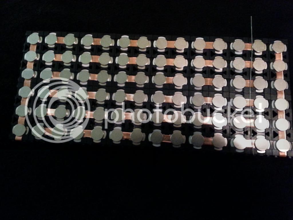
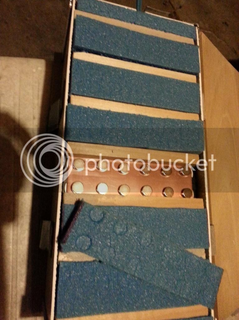
yet another solderless DIY battery pack via NIB's

radad said:
I'm finally understanding what your saying, I think. So since that is the case there is no reason to have the busbar directly on top of the battery terminal. Having a nib there instead(with the bus on top of the nib like my original idea) has many advantages. Its stronger, the busbar isn't bent all up, less likely to create a short and I can remove the battery wrapper cause my current batch of spacers is a real tight fit on the 20r batteries. If your right dnmun, and I have no reason to doubt, the nib's will carry all the parallel current without heating up at all. I'm ordering some nickel strips tonight. I'm getting closer and closer!
Synon said:
Guess I'm not completely understanding yet. How would you balance such a pack?

According to the clarification in post Aug 13, 2014 7:21 pm dnmun means in deed to have the (many) serial links first, and only weak parallel links for the small balancing currents (or half strong error currents when one cell died) - that what I meaned with "p=6 serial connections" for each of the 13+1 stages in radad's case. So, leaving out the issue of the far end connectors, this means that for a 6p14s pack you'd have 6*13=78 short ~2cm serial link strips with 2 magnets each (or 1 magnet and 1 solder contact...) and then some 13 (thin) wires or strips (soldered/welded) in lateral/parallel direction across the middle of the short serial links or so. instead of the 2x13=26 (+2) longer parallel strips, which radad has now, and 13 short serial bridges.
Is that what you want to make now, radad? With 78 short strips and 2 or 4 magnets each - all loose - this may be a like herding cats.
The "many serial links first" method makes more efforts as already mentioned by dnmun, but indeed distributes the current over more links - thus its indeed good for very high current packs; or one can use rather thin strips/wires — when soldering all contacts. For magnets yet one needs a rather huge strip area anyway and <=1C EV packs with 40..80mOhm cells (worse with aging) are rather uncritical regarding the link resistance anyway - its all about the question of the magnet contact resistance.

Both link methods yet are indifferent regarding the question of "no reason to have the busbar directly on top of the battery terminal": So or so the same full current must somehow go out of the cell into the link strip - no matter if the strip then goes serial or parallel. The magnet contacts as it are the critical spots. The direct nib-to-pole contact perhaps is stronger, but then the problem with the strip on top. Nickel strips (usually nickel covered steel strips) are somewhat ferromagnetic, but it may be not enough; a second magnet makes it complicated ... welding magnets to the strips ... We'd need some first rough milliohm resistance measurement data of the (ethanol cleaned) magnet contact options to get some overall impression.

Well, combining that — perhaps intersting could be a solution, where the many-serial-links-first method is used however to get a full flexible but rather cohesive "LEGO" assembly where each of the S*P short nickel strips ~20mm x 5mm are welded or soldered onto the minus pole of one cell and welded to one disc NIB magnet ~8mmx3mm at a distance so that the magnet fits on the next cells plus pole (Or inverse: fix strip on plus with welding only, magnet on minus). Thus one has S*P identical units to simply click together via cell holders and one pre-fixed strip+magnet per cell (which is rather stable compared to 2 magnets per strip), and then only solder some small parallel wire laterally over the middle of the strips ...
 
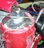
I'm interested in the magnitude of the NIB-to-cell contact resistance. Now I found one such NIB magnet here on the rush. Its a rather small 7mm x 1mm one, don't know what N-strenth but feels rather sticky and hold all kinds of small tools, needes, contact clamps etc rather aggressively in place. Yet this one seems not to be nickel covered like those on the other pics here, but some more pale aluminium or so - which would be worse electrically - I'm not sure what material. I have no fresh clean cells also right now, there was some solder on all free cells. I polished and cleaned one somewhat. Though suboptimal, I made various 4-point resistance measurements with 1A, with connections for example like this:
NIB-4PointContact_s.JPG

The first dirty results: After the contact is freshly made, after cleaning, and a after a slight lateral NIB move (which rubs oxide away) resistance is rather stable around 1 .. 2 mOhm. This is rather stable against all kinds of small micro movements, small forces, position changes, turnings etc. Lateral NIB movements and pullings even lower the resistance always a little. The resistance remains the same after an hour of total immobility.
A problem is when a stronger pressure it applied right vertical on the NIB. During the pressure the resistance is ok of course - even a little lower. But after relaxation, the resistance always goes up. Typically some factor 2, up to 3.. 4mOhm, and remains so. Any lateral movement brings it back to 1..2mOhm. (In one case with the other side of the magnet sometimes it was even up to 10mOhm - but this had to be cleaned from some darker stuff, the problem disapeared for now.)

Punx0r said:
The actual contact area between the flat magnet and the cell cap is probably not very large as the latter is probably slightly domed.

To make an extreme test of this I peeled off some of rounded side of the 18650 cell and put the magnet on there, so that it has contact only more one a line: The resistance is "only" some factor 2..3 higher.
Possible explanation: Force is not much less. Less contact area is somewhat compensated by higher local pressure. There is a law like 1/R ~ area * pressure = force (valid up to some saturation point). So there is no big problem just because of that issue.

With true nickel covered magnets, stronger magnets 8x3mm or so, clean fresh unspoiled cells, I guess the situation is somewhat better, R perhaps a factor of 3..5 reduced. Which would be ok even when R increases 2x due to the mentioned pressure relaxation problem.
So far the subject still seems interesting.

The remaining questions:
What happens with longer times of immobility; on long term with oxidation, humidity, with temperature changes ...?
 
spinningmagnets said:
A very tiny dab of the conductive paste that LFP posted should be a big improvement to keep oxygen and humidity (Galvanic corrosion?) away from the contacts.

"Conductivity improving grease project" (LFP, 3-pages)
http://endless-sphere.com/forums/viewtopic.php?f=14&t=61542

subscribed! ;) superconductive wormholes: "My objective is not to achieve parity with a soldered joint, but surpass it's conductivity."
But I guess the $200 nano tube powder is not even necessary. The magnitude of resistance promises already to stay <<5mΩ with decent strong magnet and clean nickel materials. And probably only an inert grease protection may become necessary.

I'll first watch the bare behavior until some negative effect, and then see if/how much an additive cures.
Intermediary result: After some 8h no resistance change of the unmoved contact. I'll let it for one day, then make some other tests with heat/cold maybe, then move it away from the workbench for a longer observation regarding oxidation ...

p.r.n. I'll first try simple stuff like Vaseline, which is known to block oxygen and humidity rather well is quite inert for years.
Then there are readily available active antioxidant greases with zinc particles: NOALOX Anti-Oxidant Joint Compound and PENETROX (->ebay). These also promise thinks like the nanotubes cutting oxide: "Suspended zinc particles penetrate and cut aluminum oxide; Provides additional interstrand and inter-conductor current paths for improved conductivity and cooler connections; excludes air and water ...". The zinc particles also shall act as sacrificial anode: anti_corrosive_paste . Who knows if all that is true and relevant :wink:


spinningmagnets said:
"Another No Solder/Weld 18650 Build" (snath, 6-pages)
http://endless-sphere.com/forums/viewtopic.php?f=14&t=57810

I looked at a few of these approaches which work with mechanical pressure. These require rather advanced, exact and heavy mechanics. And a little attack on the mechanics threatens the contact easily. The magnets (with some lateral fixing tape on it, and cell holders) yet are rather clingy standalone! That has the charm that quite any silly all-purpose packaging can be used as usual, some soft material & tape and then some stiff or medium stiff box/bag. The mechanical movements contribute to self-cleaning of the contacts. No lateral stress is put on the plus pole even when a pack is slightly deformed. No vertical stress as well as long as there is no strong hit from outside. Just classical laptop hard-disks need to be kept at a distance. With the prospect of some remedy against potential oxide and humidity if necessary this looks rather promising ...
 
x-speed said:
According to the clarification in post Aug 13, 2014 7:21 pm dnmun means in deed to have the (many) serial links first, and only weak parallel links for the small balancing currents (or half strong error currents when one cell died) - that what I meaned with "p=6 serial connections" for each of the 13+1 stages in radad's case. So, leaving out the issue of the far end connectors, this means that for a 6p14s pack you'd have 6*13=78 short ~2cm serial link strips with 2 magnets each (or 1 magnet and 1 solder contact...) and then some 13 (thin) wires or strips (soldered/welded) in lateral/parallel direction across the middle of the short serial links or so. instead of the 2x13=26 (+2) longer parallel strips, which radad has now, and 13 short serial bridges.
Is that what you want to make now, radad? With 78 short strips and 2 or 4 magnets each - all loose - this may be a like herding cats.
The "many serial links first" method makes more efforts as already mentioned by dnmun, but indeed distributes the current over more links - thus its indeed good for very high current packs; or one can use rather thin strips/wires — when soldering all contacts. For magnets yet one needs a rather huge strip area anyway and <=1C EV packs with 40..80mOhm cells (worse with aging) are rather uncritical regarding the link resistance anyway - its all about the question of the magnet contact resistance.

Both link methods yet are indifferent regarding the question of "no reason to have the busbar directly on top of the battery terminal": So or so the same full current must somehow go out of the cell into the link strip - no matter if the strip then goes serial or parallel. The magnet contacts as it are the critical spots. The direct nib-to-pole contact perhaps is stronger, but then the problem with the strip on top. Nickel strips (usually nickel covered steel strips) are somewhat ferromagnetic, but it may be not enough; a second magnet makes it complicated ... welding magnets to the strips ... We'd need some first rough milliohm resistance measurement data of the (ethanol cleaned) magnet contact options to get some overall impression.

Well, combining that — perhaps intersting could be a solution, where the many-serial-links-first method is used however to get a full flexible but rather cohesive "LEGO" assembly where each of the S*P short nickel strips ~20mm x 5mm are welded or soldered onto the minus pole of one cell and welded to one disc NIB magnet ~8mmx3mm at a distance so that the magnet fits on the next cells plus pole (Or inverse: fix strip on plus with welding only, magnet on minus). Thus one has S*P identical units to simply click together via cell holders and one pre-fixed strip+magnet per cell (which is rather stable compared to 2 magnets per strip), and then only solder some small parallel wire laterally over the middle of the strips ...

Yes thats what I', going to make! I can see clearly now. I been thinking all along in term of parallel first. dumun & x-speed thanks for schooling me. Maybe I'll have something worth bragging about this weekend.

x-speed I think that nib you have is zinc plated not nickel
 
This is what I understood from dnmun:


Except no parallel balance wires yet. There is one laying there on the right but not soldered to the mini bus yet. As I was getting ready to solder 13 pieces of 6 mini buses each when I realized that this was schematically/electrically the exact same as the huge bus that connected 6 positives with 6 negatives on the first pic of this thread. The only difference is a smaller balance wire and smaller bus so some small weight savings.

Before I began this project I thought power, capacity & weight were the main design objectives. But all the good info posted lately has showed me the main objective is low resistivity for both battery and connections. Isn't more copper = less resistants ? so wouldn't the larger bus (12 cells) be better for both higher current and less resistants? Of course to do the big bus I would have to have a nib directly on the battery again to clear the spacer recess, or forget the spacers altogether.
 
Love it!
 
When xspeed started talking about how corrosion for copper can be a problem for non weled/soldered connections I decided I agree. But I think it might be over a longer time frame, about the time when the cells will probably need to be replaced anyway, at that point maybe using some kind of chemical can be used on the copper contacts to keep them clean. Also corrosion is subject to air and moisture so keeping the pack minimally exposed can make all the difference. Still I guess gut shot views aren't the best way to go by, maybe their is some kind of copper,nickle corrosion/resistance over time in room environment chart or something of that nature out there on the net.
 
radad said:
TheBeastie Did you ever get your batteries from fasttech?
Funny you should ask, I have placed a video of me opening my first fasttech package, on youtube, its unlisted atm and if I get my paypal refund I will take it off as I don't believe in making companies look bad if properly compensated.

This was for the most part a small test order to see how it goes.. well it didn't go very well. I was somewhat surprised when I got it though, a lot of people on the net forums are claiming around 2.5 months for 18650 cells from fasttech now, I got mine in about 5 weeks.

I ordered a total of 6 18650 cells I only got 2, and one of them is severely/dangerously deformed. I also ordered some rosin flux which has been heavily exposed and pre-opened with crystals/powder over the entire contense of the parcel making it all sticky and nasty.
Everything had been opened by some one, even the little bags for the switches were ripped opened and put back in.
I can only guess what happened, one theory is it got stuck in a Malaysia Post conveyor belt (maybe deliberately) then got run over repeatably with a fork lift. Maybe it was all accident or maybe it was deliberate as some one was interested to see what was inside.
Maybe it was an elaborate deliberately poorly packaged parcel from fasttech to snake out of sending me all my 18650 cells (and sending just 2 stuffed ones), I will never know.
 
ahh My baby, isn't she beautiful!


I'm guessing i need only to balance as shown. Not every parallel row. Thats heavy duty aluminum foil folded over 8x for balance connections. Thats positive on the left.
 
I would not use aluminium with either copper or nickel as you risk galvanic corrosion. See how far apart they are on this table:

http://www.engineeringtoolbox.com/electrode-potential-d_482.html

Metals that have less voltage potential between them (are close together on the table) fair well.
 
I made further and longer tests on the NIB-cell contact of that "worst case" scenario (1mm x 7mm NIB, material questionable, used re-cleaned cell surface) continuing post Fri Aug 15, 2014 5:46 pm :

A contact of initially 1.3mOhm remained stable at that value (<1.4mOhm) for 3days of immobility! Lateral movements then increased the average resistance somewhat to 2mOhm - unlike in the beginning after cleaning where the lateral movements always decreased resistance in average. (-> This may be due to oxidation of off-contact locations over days?).

Cleaning with mild acid and then Ethanol again improved the contact slightly.

Increasing the temperature by some 15°C and then cooling again repeatedly had no significant effect (<5%).

Sanding: Immediately after sanding both contact sides with fine sandpaper the resistance goes up very high to some 10mOhm .. 80mOhm (!), strongly varying randomly even after lateral movements. (-> granular dirt). When the contact yet is cleaned after sanding, the resistance goes down to lowest values (~1mOhm), and there is a rather low variance.

=> Theory: Fine spikes in the surface create stronger pressure microscopically, which minimizes surface contamination resistance. Background: To establish a electrical pressure contact first minimal contamination layers need to be penetrated (threshold range), then begins the linear range where conductivity is proportional to the force, up to some saturation range where stronger pressure doesn't add much more conductivity anymore.

A first test with Vaseline was done, and it seems to be very positive: The resistance does not go up measurably! (I expected a slight increase with any material present inside the contact). And the wanted effect: The variance of the resistance goes down even more. So there appears to be a rather reliable/constant low resistance of the contact after even after half a day of immobility plus then random movements. After the initial clip of the contact a initial lateral rubbing movement is less needed - because oxidation is probably blocked as soon as the Vaseline stuff is on the surface (May depend on a very quick application of Vaseline after cleaning). And even the adverse effect of pressure + release as described in the other post seems to be much less. But have to watch it over days. The sealing effect (keeping away oxygen and humidity) of the Vaseline yet seems to be obvious.

"Battery terminal grease" as used for car battery poles however promises to be even more appropriate - I learned after some reading: Contains corrosion stoppers in addition to inert Vaseline/hydrocarbons. That is the standard stuff used for such purpose. I'll get some.


Summary and plan so far as I see it:

* This "low force big area clip contacts" via NIB magnets really seem to feasible for that ~3A currents which we have with 18650 cells for EVs. At least with some care as described below the situation is robust enough to have adverse effects slow enough to watch it over weeks.

* Nickel should be preferred as surface material on all movable contacts involved: no galvanic corrosion potential; nickel is the cheap & good proven material for moveable contacts.

* Essential is an initial cleaning mechanically and with ethanol / acetone / soap / tenside stuff. Fat, dirt, dust and any granular stuff MUST go out before the final clip, otherwise there is unacceptable high variance/random in contact resistance.

* Optionally beneficial seems to be a fine sanding of the contact surfaces plus a mild acid deoxidation (vinegar essence; <<5% HCl; ...) - before the last cleaning step.

* Essential on the long run may be to use a blocker for oxygen and humidity, possibly with corrosion blocker: (Technical) Vaseline / Battery terminal grease. More advanced stuff like NOALOX, PENETROX, carbon nanotubes .. may only be necessary for aluminium and other materials with tough oxide layers.). To be investigated more.

* The magnet polarity possibly should be varied in alternating style like colors on a chess board to not create a huge magnetic dipole which distorts for example a smart phone compass over a far distance.

* After the final clip of the contact a small lateral movement of the contact forth and back should be made to rub away any recreated thin oxide areas.

* Essential is to REALLY MEASURE the contact resistances and its variance over a significant number of contact sample spots in the pack after the assembly. What is not measured and felt out will not work stable on the long run. The measurements to be repeated after a day / week / month ... of pack usage in the beginning.


So I will order magnets, select the cells and a reliable (chinese) source for the next pack. This may take some time.

Main objective for me: pack can be reconfigured / extended / single cells tested & replaced rather easily at any time. (Though I have already a DIY welding setup.)
 
radad said:
ahh My baby, isn't she beautiful!

That "serial-first" assemply looks good. How does it feel regaring mechanical stability and practicability vs the previous longer parallel-first bars? or are both beyond doubt?

I think the extra magnets for the alu foil will not really turn out practical. too extensive - when thinking about the coverage with tape & soft material etc. And alu indeed is a worst material for moveable contacts. Perhaps any thin ferromagnetic nickel-steel strip may do the small balancing currents without extra magnets, when no soldering ist wanted? I think about using even very thin coil wire spot soldered: That may act as a sort of fuse in many situations where erroneous strong lateral currents want to flow.

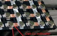
I'd be most interested in the contact resistance between the cell and the copper strip (and/or future nickel strip) of this assembly with indirect magnetic force. This could be measured easily with a voltmeter in an assembled pack like this: While the pack is charging (or discharging) with a known amperage, measure in the most sensible millivolt range of the voltmeter ("200mV" range typically), connecting the standard probes (or needles + alligator clips) with only small pressure at spots like in the picture below:

NIB6x14 contact resistance.jpg


For example, if there is 1.2mV measured this way and charge amperage is 6A for the 6p pack, there would go 6A / 6 = 1.0A through each cell and each copper strip. And the cell-strip contact resistance would be R_contact = 1.2mV / 1.0A = 1.2mOhm.
(You could then see how this value varies with nickel vs copper, with cleanings, terminal grease, how it varies over the pack, over time etc ... as mentioned in the above post.)


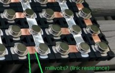
Similarly you could for comparison measure the mere link strip resistance like this (multiply with 1.5 to estimate for hidden length):

NIB6x14 link resistance.jpg

For 12mm * 0.15mm x 8mm copper I'd expect a copper link resistance of just R_link = 0.012m / 0.00015m / 0.008m / 50,0 · 106 A/Vm = 0.2mOhm ! Hardly even measurable with a standard multimeter's 0.1mV resolution!
So this would be negligible compared to the Ri-DC of the 10C Samsung 18650-20R cell ( 30mOhm [new] .. 70mOhm [when old]). Normal 2C .. 3C cells for EV have even more Ri. And its also negligible compared to the cell-strip connection resistance estimated in the range 0.5 .. 2mOhm.
Thus nickel would be good as well regarding resistance (1.0mOhm instead of 0.2mOhm with same thickness), but a lot better for movable contacts and magnetically. Even parallel-first connection scheme would not affect the situation much. Its simply a matter of the sum: Rtotal_per_cell = 50mOhm + 1.0mOhm + 2 * 1.2mOhm = 53.4mOhm. So the real question is about the reliability of the magnetic pressure contact.

The 18650-20R cells are rather "racing cells", designed for full discharge in less than 15 minutes, in power tools etc ... not so much for high capacity in normal EVs. I wonder how many amperes you want to draw? If that setup is really intended for high currents, the magnet contact resistances should be checked extra carefully.
 
x-speed said:
I made further and longer tests on the NIB-cell contact of that "worst case" scenario (1mm x 7mm NIB, material questionable, used re-cleaned cell surface) continuing post Fri Aug 15, 2014 5:46 pm :

A contact of initially 1.3mOhm remained stable at that value (<1.4mOhm) for 3days of immobility! Lateral movements then increased the average resistance somewhat to 2mOhm - unlike in the beginning after cleaning where the lateral movements always decreased resistance in average. (-> This may be due to oxidation of off-contact locations over days?).

Cleaning with mild acid and then Ethanol again improved the contact slightly.

Increasing the temperature by some 15°C and then cooling again repeatedly had no significant effect (<5%).

Sanding: Immediately after sanding both contact sides with fine sandpaper the resistance goes up very high to some 10mOhm .. 80mOhm (!), strongly varying randomly even after lateral movements. (-> granular dirt). When the contact yet is cleaned after sanding, the resistance goes down to lowest values (~1mOhm), and there is a rather low variance.

=> Theory: Fine spikes in the surface create stronger pressure microscopically, which minimizes surface contamination resistance. Background: To establish a electrical pressure contact first minimal contamination layers need to be penetrated (threshold range), then begins the linear range where conductivity is proportional to the force, up to some saturation range where stronger pressure doesn't add much more conductivity anymore.

A first test with Vaseline was done, and it seems to be very positive: The resistance does not go up measurably! (I expected a slight increase with any material present inside the contact). And the wanted effect: The variance of the resistance goes down even more. So there appears to be a rather reliable/constant low resistance of the contact after even after half a day of immobility plus then random movements. After the initial clip of the contact a initial lateral rubbing movement is less needed - because oxidation is probably blocked as soon as the Vaseline stuff is on the surface (May depend on a very quick application of Vaseline after cleaning). And even the adverse effect of pressure + release as described in the other post seems to be much less. But have to watch it over days. The sealing effect (keeping away oxygen and humidity) of the Vaseline yet seems to be obvious.

"Battery terminal grease" as used for car battery poles however promises to be even more appropriate - I learned after some reading: Contains corrosion stoppers in addition to inert Vaseline/hydrocarbons. That is the standard stuff used for such purpose. I'll get some.


Summary and plan so far as I see it:

* This "low force big area clip contacts" via NIB magnets really seem to feasible for that ~3A currents which we have with 18650 cells for EVs. At least with some care as described below the situation is robust enough to have adverse effects slow enough to watch it over weeks.

* Nickel should be preferred as surface material on all movable contacts involved: no galvanic corrosion potential; nickel is the cheap & good proven material for moveable contacts.

* Essential is an initial cleaning mechanically and with ethanol / soap / tenside stuff. Fat, dust and any granular stuff MUST go out before the final clip, otherwise there is unacceptable high variance/random in contact resistance.

* Optionally beneficial seems to be a fine sanding of the contact surfaces plus a mild acid deoxidation (vinegar essence; <<5% HCl; ...) - before the last cleaning step.

* Essential on the long run may be to use a blocker for oxygen and humidity, possibly with corrosion blocker: (Technical) Vaseline / Battery terminal grease. More advanced stuff like NOALOX, PENETROX, carbon nanotubs .. may only be necessary for aluminium and other material with tough oxid layers.). To be investigated more.

* The magnet polarity possibly should be varied in alternating style like colors on a chess board to not create a huge magnetic dipole which distorts for example a smart phone compass over a far distance.

* After the final clip of the contact a small lateral movement of the contact forth and back should be made to rub away any recreated thin oxide areas.

* Essential is to REALLY MEASURE the contact resistances and its variance over a significant number of contact sample spots in the pack after the assembly. What is not measured and felt out will not work stable on the long run. The measurements to be repeated after a day / week / month ... of pack usage in the beginning.


So I will order magnets, select the cells and a relyable (chinese) source for the next pack. This may take some time.

Mean objective for me: pack can be reconfigured / extended / single cells tested & replaced rather easily at any time. (Though I have already a DIY welding setup.)

Wow nice contribution Xspeed! I knew this would work the first time I went down the road on a temp foam/duct tape clamping system. Just didn't have the equipment & expertize to prove it. How are you measuring milliohms ? is it off the shelf or diy? Also could I calculate the entire packs resistance by the voltage drop at full throttle?

Ideal size magnets 12x3mm or 1/2x1/8" for use with spacers. Without spacers 3/8" is fine. N50's are to expensive. n35-n45 cheap and plentiful and very strong. I've test nib's @120vmax and 7amps max no problems. For sure impossible to extremely hard to solder without losing magnetism. Either or both sides of bus works ok.

PLEASE I'm still asking if some can print me some 3d spacers from a stl file at a reduced cost??????????????

I'm still pondering dnmun serial first type connections that he described. With the small balance wire being used, if a cell dies wouldn't it be taxed to try and maintain balance in that parallel group. I also assume that without the balance wire if a cell dies that whole serial group dies with it? It seems to me the larger busbar (lets call it 2x6) is the same thing as dnmun described just in overkill form.

I see snaths pack build as being the best diy build based solely on his copper bus. I'm thinking of copying his copper bus idea to one solid piece to cover 6 +'s and 6-'s. I think that is the best connection method. If you got a parallel bank capable of 120amps why not try and get closer to that number than 30amps? The 12 indentations should be larger to accommodate a nib. Best of both worlds. The nib's should be 1mm above the surface of the bus. Then a simple silicone baking mat placed over the top of the nib's, foam on that, and in a box with a lid top & bottom. I agree nickel is the way. Weather or not that piece can be made of nickel is questionable.
 
x-speed said:
radad said:
ahh My baby, isn't she beautiful!

That "serial-first" assemply looks good. How does it feel regaring mechanical stability and practicability vs the previous longer parallel-first bars? or are both beyond doubt?

I think the extra magnets for the alu foil will not really turn out practical. too extensive - when thinking about the coverage with tape & soft material etc. And alu indeed is a worst material for moveable contacts. Perhaps any thin ferromagnetic nickel-steel strip may do the small balancing currents without extra magnets, when no soldering ist wanted? I think about using even very thin coil wire spot soldered: That may act as a sort of fuse in many situations where erroneous strong lateral currents want to flow.

I'd be most interested in the contact resistance between the cell and the copper strip (and/or future nickel strip) of this assembly with indirect magnetic force. This could be measured easily with a voltmeter in an assembled pack like this: While the pack is charging (or discharging) with a known amperage, measure in the most sensible millivolt range of the voltmeter ("200mV" range typically), connecting the standard probes (or needles + alligator clips) with only small pressure at spots like in the picture below:

View attachment 1


For example, if there is 1.2mV measured this way and charge amperage is 6A for the 6p pack, there would go 6A / 6 = 1.0A through each cell and each copper strip. And the cell-strip contact resistance would be R_contact = 1.2mV / 1.0A = 1.2mOhm.
(You could then see how this value varies with nickel vs copper, with cleanings, terminal grease, how it varies over the pack, over time etc ... as mentioned in the above post.)


Similarly you could for comparison measure the mere link strip resistance like this (multiply with 1.5 to estimate for hidden length):


For 12mm * 0.15mm x 8mm copper I'd expect a copper link resistance of just R_link = 0.012m / 0.00015m / 0.008m / 50,0 · 106 A/Vm = 0.2mOhm ! Hardly even measurable with a standard multimeter's 0.1mV resolution!
So this would be negligible compared to the Ri-DC of the 10C Samsung 18650-20R cell ( 30mOhm [new] .. 70mOhm [when old]). Normal 2C .. 3C cells for EV have even more Ri. And its also negligible compared to the cell-strip connection resistance estimated in the range 0.5 .. 2mOhm.
Thus nickel would be good as well regarding resistance (1.0mOhm instead of 0.2mOhm with same thickness), but a lot better for movable contacts and magnetically. Even parallel-first connection scheme would not affect the situation much. Its simply a matter of the sum: Rtotal_per_cell = 50mOhm + 1.0mOhm + 2 * 1.2mOhm = 53.4mOhm. So the real question is about the reliability of the magnetic pressure contact.

The 18650-20R cells are rather "racing cells", designed for full discharge in less than 15 minutes, in power tools etc ... not so much for high capacity in normal EVs. I wonder how many amperes you want to draw? If that setup is really intended for high currents, the magnet contact resistances should be checked extra carefully.

I had to glue the crappy 18650 spacers together with crazy glue. Now I have a somewhat rigid grid to work with. Previous pack config with longer parallel buses was more prone to popping out a nib when being flexed. Now do to the crazy glue and shorter bus length its much more mechanically solid. I can't pop one out with hand pressure now.

My multi meter only goes to 200 ohm range. Lowest I can measure is .2 I think thats 200milliohms.

My current setup only draws 22amps. New controller I'm looking at now is 30amps. EV motor cycle is next on my list. So i'm kinda looking forward at that in this design.
 
radad said:
I knew this would work the first time I went down the road on a temp foam/duct tape clamping system. Just didn't have the equipment & expertize to prove it. How are you measuring milliohms ? is it off the shelf or diy? Also could I calculate the entire packs resistance by the voltage drop at full throttle?
radad said:
My multi meter only goes to 200 ohm range. Lowest I can measure is .2 I think thats 200milliohms.
Measuring the contact and/or link resistance is as easy as described in the second post yesterday with the 2 pics - there is no DIY project to do, simply measure voltage drops while a significant current flows through the pack: You do not use the ohm ranges at all on the multimeter! but: Simply charge the whole pack at a known / constant amperage as usual. Then while the current is flowing through each contact (divided by 6 in a 6p pack if the whole situation is symmetric and balanced) measure the millivolts in the most sensitive voltmeter range over the contact; or over a link; or over 2 contacts plus link for added resistances .... The resitance in question is R_path = U_drop / I_path as explained in the above calculation example. Its really rather simple - particularly in the serial-first link geometry. Ask back in case ...

The effective (DC) resistance of the entire pack is R_total_per_cell * S / P.

So if for example R_total_per_cell (including the dominating cell Ri, the contacts and the link) is 50mOhm + 2*1mOhm + 1mOhm = 53mOhm, then the pack resistance is 53 * 14 / 6 = 124mOhm.
The voltage drop at 22A then is about 22A * 0.124Ohm = 2.7Volts . That would be good, small compared to the 52V pack voltage.

So just the magnet contact resistances should stay reliably smaller than 5mOhm - thats the main point.

radad said:
Ideal size magnets 12x3mm or 1/2x1/8" for use with spacers. Without spacers 3/8" is fine. N50's are to expensive. n35-n45 cheap and plentiful and very strong.
I've test nib's @120vmax and 7amps max no problems. For sure impossible to extremely hard to solder without losing magnetism. Either or both sides of bus works ok.
Yes soldering the magnets is probably no go (Could be tested still however to get a feeling how quick magnetism is lost really). Yet spot welding plus one magnet per cell for me is still a option to be considered as described in a post a week back or so. Not decided yet, I'll first check the indirect magnet contact through strips also when I have the better magnets and strip material and new cells. Hope you will also provide some resistance measurements for the assembly you have, so that there is more data to get a feeling ...

radad said:
PLEASE I'm still asking if some can print me some 3d spacers from a stl file at a reduced cost??????????????
I wonder If that really makes a big improvement. I doubt you will get this at a reasonable price. This standard spacers look good, and are can be put together flexibly. The possible width of link strip with that spacers is more than enough, as explained in the R_total_per_cell estimation above.

radad said:
I'm still pondering dnmun serial first type connections that he described. With the small balance wire being used, if a cell dies wouldn't it be taxed to try and maintain balance in that parallel group. I also assume that without the balance wire if a cell dies that whole serial group dies with it? It seems to me the larger busbar (lets call it 2x6) is the same thing as dnmun described just in overkill form.
I see snaths pack build as being the best diy build based solely on his copper bus. I'm thinking of copying his copper bus idea to one solid piece to cover 6 +'s and 6-'s. I think that is the best connection method. If you got a parallel bank capable of 120amps why not try and get closer to that number than 30amps? The 12 indentations should be larger to accommodate a nib. Best of both worlds. The nib's should be 1mm above the surface of the bus. Then a simple silicone baking mat placed over the top of the nib's, foam on that, and in a box with a lid top & bottom.
This way?:
click

Thats a parallel-first assembly, effective resistance is a little higher, but that would be also uncritical for these EV currents 0.5C .. 2C. Really you are worrying too much about the link geometry & material as it - for just 22 .. 30Amps. The magnet contact resistance as it is still the issue of question. Choose the geometry which feels best mechanically / for magnets.

I think the indentations are mainly needed in snath's approach to apply a reliable strong pressure when using such mechanical elastic screwing method. The charm off the NIB method however is to have it rather simple, and elasticity is not critical here: The magnets follow any small bending and mechanical stress. So I think I'll avoid such sophisticated markings and sophisticated mechanics if the magnets stay in place so with just some tape & cover (and this seems so), I'll rather go for thin strips (as link resistance is quite uncritical - particularly with serial-first) and simple setup.

radad said:
I agree nickel is the way. Weather or not that piece can be made of nickel is questionable.
As you already have the copper strips, copper might be ok also when the oxygen and humidity is blocked on the mid / long run as described. Just needs to be measured ...
 
radad said:
I had to glue the crappy 18650 spacers together with crazy glue. Now I have a somewhat rigid grid to work with. Previous pack config with longer parallel buses was more prone to popping out a nib when being flexed. Now do to the crazy glue and shorter bus length its much more mechanically solid. I can't pop one out with hand pressure now.
I cannot really imagine that the magnets jump off easily in either case - when some decent soft cover and tape is on top, and the pack fixed reasonably against strong bending. With a 0.1mm foil between cell and magnet even my small 1x7mm magnet sticks still rather aggressively. Was this problem perhaps with your initial very thick copper strips?

radad said:
My current setup only draws 22amps. New controller I'm looking at now is 30amps. EV motor cycle is next on my list. So i'm kinda looking forward at that in this design.
So these are rather small currents for these Samsung20R (10C) power tool /racing cells. Just 1.0 .. 1.5C . Even high cap laptop cells would do. Link strips can remain rather thin.
 
radad said:
ahh My baby, isn't she beautiful!


I'm guessing i need only to balance as shown. Not every parallel row. Thats heavy duty aluminum foil folded over 8x for balance connections. Thats positive on the left.

just got back here and this is how i was thinking about the direction the major current flows. but i always use the minimum dimension conductors too. did not mean to weird out your thread but i got to thinking about how backwards it was when i saw ecross with his huge twisted pair.

then the idea that heating may be less risk if it can be minimized to the edge of the case, again assuming and expecting that the thermal link from the anode cap to the cell inside the can is able to protect the anode end of the cell.

it will be really interesting to see how this works. one thing to observe is how the stiffness and size of the conductors makes the contacts to those planar end surface limited. it is almost as if you could use some of that flexible conductor traces they use for making the ribbon cable like stuff inside electronics out of. use the flexible link for the series links and then the magnet would be able to force more contact area perhaps. the cans could flex with respect to each other and not lose continuity.

BOL.
 
Well I'm on battery pack rev 5.21 and I'm finally happy. X-speed I took your advice and did what mechanically felt best. On ver 5.20 (series first w/22ga balance wire) worked great except it blew out 4 balance wires during assembly (damm magnets), so I can assure that the balance wire will act as a fuse with the lateral current. I currently have kung fu fingers from screwing with these magnets for so long. Also on ver 5.20 the small series connectors still wanted to come loose on hard impacts.

5.20


The stock spacers are crap, to flexible, break easy etc. I took some 3m body molding tape and placed 3/8" sq. poplar across the pack width. This stiffened/strengthened it up dramatically. No more breaks in contacts at all, even curb/log jumping. It also served to create a fence so magnets cannot jump across and short out.

5.21
Mechanically the strongest setup I've tried is the original big bus (6+'s & 6-'s)so that has once gain become new ver 5.21. It survived some severe punishment today and never missed a beat. 3 miles @ full throttle the pack didn't even feel warm. Yes the magnets are back on the battery terminals again, no problems, no heat, better connection by far.
Wattsup meter reports:
22.28 A max
1223 W max
10 miles @ 1/3 pedal & 2/3 motor = 2.61Ah/143Wh

Standing volt at start 58.6, under 22.28A load, voltage dropped to 56.2v. My first build voltage dropped from 58.x to like 52.x with the same load.so I think the numbers are good?

Xspeed I tried to measure what you showed and got 0.00 @200mvolt setting?
 
radad said:
Wattsup meter reports:
22.28 A max
1223 W max
10 miles @ 1/3 pedal & 2/3 motor = 2.61Ah/143Wh

Standing volt at start 58.6, under 22.28A load, voltage dropped to 56.2v. My first build voltage dropped from 58.x to like 52.x with the same load.so I think the numbers are good?

that 2.4v drop would be near the 2.7v calculation above (which assumed a somewhat aged Samsung20R cell 50mOhm vs 30mOhm new). So it cannot be totally off-key. From that result alone some 0.5 .. 30mOhm contact resistances per cell in average could be estimated ;) Rather huge range of uncertainty. However it should be known by resistance mearement, if the contact resistances of this indirect magnetic copper-cell contact really are <5mOhm - and rather constant without exception, thus reliable.
Its not enough that the pack remains rather cool on 3 miles to tell about a acceptable contact resistance which doesn't double the pack resistance. You have low-R cells. The pack has a heat capacity. The fact there was a 6V drop (with thick strips I guess) indicates, that the problem is not too far away. Did you do any surface cleaning/preparation?

radad said:
Xspeed I tried to measure what you showed and got 0.00 @200mvolt setting?

Well, I guess something was done wrong/incomplete. At 200mVolt range a simply multimeter would show "00.0" mV. A 4+ digit voltmeter would hardly show zero anyway.
What exactly did you do? Did you really have a charge current flowing through the pack while sensing the mvolt drop over a contact? How much charge current? Even if the charge current was very low, for example 1.0A , divided for 6p then with a very good contact of 1.0mOhm the drop would be still 1.0mOhm * 1.0A/6 = 00.2mV displayed. So that should still be beyond zero, 1 oder 2 digits. But perhaps ...

Use more charge churrent if possible. Measure different contacts. Measure the drop over a complete link (over 2 contacts plus link strip) completely (sense + on a plus pols and - on the linked minus pole). There should shurely be a non-zero mvolt drop, so that you see something to start with.
If with significant current flowing the drop is really below multimeter resolution everywhere , which I totally cannot believe, and charger current is rather limited, then you could get more current per link by experimenting with a 1p or 2p pack temporarily, so that the current is less divided and higher per link.

I got new magnets now with nickel and made first tests on a new cell. The contact resistances etc results are similar as in the previous experiments with the "dirty" materials. Still to experiment more when I have time.

Note: A soldering test on a magnet resulted in immediate loss of most of the magnetism - rather as expected.
 
x-speed said:
radad said:
Wattsup meter reports:
22.28 A max
1223 W max
10 miles @ 1/3 pedal & 2/3 motor = 2.61Ah/143Wh

Standing volt at start 58.6, under 22.28A load, voltage dropped to 56.2v. My first build voltage dropped from 58.x to like 52.x with the same load.so I think the numbers are good?

that 2.4v drop would be near the 2.7v calculation above (which assumed a somewhat aged Samsung20R cell 50mOhm vs 30mOhm new). So it cannot be totally off-key. From that result alone some 0.5 .. 30mOhm contact resistances per cell in average could be estimated ;) Rather huge range of uncertainty. However it should be known by resistance mearement, if the contact resistances of this indirect magnetic copper-cell contact really are <5mOhm - and rather constant without exception, thus reliable.
Its not enough that the pack remains rather cool on 3 miles to tell about a acceptable contact resistance which doesn't double the pack resistance. You have low-R cells. The pack has a heat capacity. The fact there was a 6V drop (with thick strips I guess) indicates, that the problem is not too far away. Did you do any surface cleaning/preparation?

radad said:
Xspeed I tried to measure what you showed and got 0.00 @200mvolt setting?

Well, I guess something was done wrong/incomplete. At 200mVolt range a simply multimeter would show "00.0" mV. A 4+ digit voltmeter would hardly show zero anyway.
What exactly did you do? Did you really have a charge current flowing through the pack while sensing the mvolt drop over a contact? How much charge current? Even if the charge current was very low, for example 1.0A , divided for 6p then with a very good contact of 1.0mOhm the drop would be still 1.0mOhm * 1.0A/6 = 00.2mV displayed. So that should still be beyond zero, 1 oder 2 digits. But perhaps ...

Use more charge churrent if possible. Measure different contacts. Measure the drop over a complete link (over 2 contacts plus link strip) completely (sense + on a plus pols and - on the linked minus pole). There should shurely be a non-zero mvolt drop, so that you see something to start with.
If with significant current flowing the drop is really below multimeter resolution everywhere , which I totally cannot believe, and charger current is rather limited, then you could get more current per link by experimenting with a 1p or 2p pack temporarily, so that the current is less divided and higher per link.

I got new magnets now with nickel and made first tests on a new cell. The contact resistances etc results are similar as in the previous experiments with the "dirty" materials. Still to experiment more when I have time.

Note: A soldering test on a magnet resulted in immediate loss of most of the magnetism - rather as expected.

My new 20r are measuring right around 50mohm.
I just learned this: ri=(v1-v2)*r/v2
v1 = 3.63
v2 = 3.61
r = 10ohm/10w ceramic
I've read 20r's are anywhere from 13mohm to 50mohm. But I'm seeing a consistent 50mohms.

The measurements you instructed I tried with a 5 amp charge current, so I don't know what happened. I see no way to measure a 20a load on a moving bike LOL. Even with the wheel propped up is just a couple amps too, so I can't think of a test to really load it. I just starting to understand some of this mathematically, so excuse my ignorance. Also the initial 6v voltage drop was on an entirely different pack build last year, different batteries and contacts. I've had 5 different enclosures and 21 different contacting methods thus 5.21

Ver 5.21

I don't see it getting any better, except for some cu-ni goop for the contacts.
 
radad said:
My new 20r are measuring right around 50mohm.
I just learned this: ri=(v1-v2)*r/v2
v1 = 3.63
v2 = 3.61
r = 10ohm/10w ceramic
I've read 20r's are anywhere from 13mohm to 50mohm. But I'm seeing a consistent 50mohms.

The math is right for a 10ohm load test v measured directly on the cell terminals.
Yet see the resolution: the drop v1-v2 is just 0.02v with bad resolution/accuracy on your multimeter. the drop could be more near 0.01v, thus the result near 30mOhm. or near 0.03 ... then a lot higher.

(You could measure the voltage drop more exactly by subtracting ~3.6v constant from the measured voltage by use of another unloaded Li cell in anti-series connection with your multimeter wires, and then switching the multimeter down to the 200mV range, thus 0.1mV resolution instead of 10mV ...)

radad said:
The measurements you instructed I tried with a 5 amp charge current, so I don't know what happened. I see no way to measure a 20a load on a moving bike LOL. Even with the wheel propped up is just a couple amps too, so I can't think of a test to really load it. I just starting to understand some of this mathematically, so excuse my ignorance. Also the initial 6v voltage drop was on an entirely different pack build last year, different batteries and contacts. I've had 5 different enclosures and 21 different contacting methods thus 5.21

hmm, with 5A / 6 = 0.83A current per cell you should definitely see values beyond 00.0 mV measuring over a contact. 5A should be enough. 00.0 can be bug, missunderstanding, or extremly low value...
Yet I really can't belief R_contact to be less than 00.1mV / 0.83A = 0.12mOhm consistently from what I have experienced! Though you have strong magnet power with the 2 rather big ones per contact. The copper in addition will likely cover with thin oxide quickly etc.
The exact picture of the measuring/sensing situation would tell ...

The contact resistance and its variance yet are the key points of all this. Without knowing & rechecking that quantitatively (repeatedly) matters and modifications remain questionable.

radad said:
Ver 5.21
I don't see it getting any better, except for some cu-ni goop for the contacts.

How thick is the wide-areal copper here? It seems rather stiff, with danger of only random strength contacts?
Does it feel like really having good effective pressure on all contacts?
Unfortunatly contact R can hardly be measured in this geometry - a high-res cell voltage logging while driving would be need to quantify the situation electrically.
A rather thin foil would do perhaps. But when the round going power tape and outer box provide mechanical stability, I don't see a reason against the thinner bars which would be supported laterally right by the cuts in the cell holders.? (less a matter if parallel first or serial first)
 
x-speed said:
with 5A / 6 = 0.83A current per cell you should definitely see values beyond 00.0 mV measuring over a contact.

perhaps the battery was already fully charged or deep in the CV phase - 5A not actually flowing / measured / known at the time of the mV reading?
=> measure at beginning of charge after significant discharge.

(artificial discharge could be done e.g. with one or more (parallel) electric irons (some 1..3A per iron ), with 4x 12v Halogen , ... )

Besides: With your one cell at 10 Ohm discharge experiment you could also learn and get familiar with measuring the low-R milliohm resistances of cables/contacts: 3.61V / 10Ohm = 0.361A are flowing. The drop of 0.02v = 20mv over ON/OFF along time axis means the 20mv / 0.361A = 55mOhm (resolution +/- 27mOhm) which you already calc'ed.
Now while the 0.361A are flowing you could also measure directly in 200mV range the voltage drop over a cable used, over a contact used, over 2 contacts + cable section (which sums up) etc.
For example the drop over some cable section is 2.5mV. Then the cable piece resistance is 2.5mV / 0.361A = 7mOhm. The same with the mv drop over a contact. Always the same principle: Sending some known/measured current high enough through some (linear) resistive thing, and measure the mv drop.
Without being familiar with that kind of thing, contact experiments remain grey.
 
x-speed said:
x-speed said:
with 5A / 6 = 0.83A current per cell you should definitely see values beyond 00.0 mV measuring over a contact.

perhaps the battery was already fully charged or deep in the CV phase - 5A not actually flowing / measured / known at the time of the mV reading?
=> measure at beginning of charge after significant discharge.

(artificial discharge could be done e.g. with one or more (parallel) electric irons (some 1..3A per iron ), with 4x 12v Halogen , ... )

Besides: With your one cell at 10 Ohm discharge experiment you could also learn and get familiar with measuring the low-R milliohm resistances of cables/contacts: 3.61V / 10Ohm = 0.361A are flowing. The drop of 0.02v = 20mv over ON/OFF along time axis means the 20mv / 0.361A = 55mOhm (resolution +/- 27mOhm) which you already calc'ed.
Now while the 0.361A are flowing you could also measure directly in 200mV range the voltage drop over a cable used, over a contact used, over 2 contacts + cable section (which sums up) etc.
For example the drop over some cable section is 2.5mV. Then the cable piece resistance is 2.5mV / 0.361A = 7mOhm. The same with the mv drop over a contact. Always the same principle: Sending some known/measured current high enough through some (linear) resistive thing, and measure the mv drop.
Without being familiar with that kind of thing, contact experiments remain grey.

X-speed thanks so much for your major contributions!!!

Ok I got some mv measurements from cell to cu - lowest 1.5mv, highest 3.4mv. Most are right at 2.0mv avg 2.2mv (10 points tested). Upon cleaning the 3.0+contacts mv dropped to around 2mv. So I assume that 1.5mv is a prefect contact point? The link resistance is still reading 0.00. Think I'm going to get some acetone today and clean all contact points.
 
Back
Top