Zero factory pics

sk8norcal

1 MW
Joined
May 16, 2010
Messages
2,995
Location
San Jose, CA
http://www.gizmag.com/zero-electric-motorcycles-factory-2015/35865/

http://www.gizmag.com/zero-electric-motorcycles-factory-2015/35865/pictures#29

zero-motorcycles-2015-full-range-review-81.jpg
 
So why not go up to a higher voltage that would work with the existing charging infrastructure? "If we went to 300 volts, it would hurt you on every front that matters," says Zero's Senior Battery Specialist Luke Workman. "We'd have lower efficiency, lower power, higher cost, higher drive train heat – and in terms of life safety for the guys that are working on these things, you go from a nasty tickle … to dead. The majority of electric vehicles that are using higher voltages are doing so simply because they've been designed using legacy equipment. You'll see a lot more EVs going low voltage in the future."

Low voltage, high current batteries?!

Yes, please ..this will change everything.
 
Zero needs to throw the sevcons in the dumpster and build their own controller with a built in charger. The controller fets and charger fets can share the same heat sink (not a complex AC propulsion type charger which uses the same switching devices for charging and motor drive). This will enable fast fast charging with little weight penalty. Forget DC charging on a bike for a few years. We need at least a 6.6kw AC charger j1772 now, standard and onboard. With an adapter we can plug into a dryer outlet or rv outlet or use a two independent 110 sockets (quick 220 coverter)

You can buy a high quality 7.7kw made in usa clipper creek j1772 charger for 500 bucks. Probably about the same price you buy a single chademo connector for. Even if you succeed and force DC charger manufactures to make their chargers work at low voltage like the spec says (good luck), does it make semse to use a 800V rated connector on a 100v bike? Maybe. CCS has the same problem. Too big. The North American Tesla supercharger connector is the only one that makes sense in the usa. Tesla mennekes type 2 for europe might work for a motorbike.

You have about 2 years until Honda and Yamaha releases their bikes. You have first mover advantage which is huge. Don't waste the opportunity to become the next Tesla and take on the old guard. Next year's bike has to be the game changer. No more incremental improvements.
 
Very interesting. Low voltage, high current, small drive wheel. It sounds like ES ;)


If you ask a motorcycle buyer what their thoughts on electric bikes are, most will tell you range is one of their biggest concerns.

"If we did nothing else, we could put a fairing on and increase our range by 30 percent."

Sounds like something that should have already been done 5 years ago ;)
 
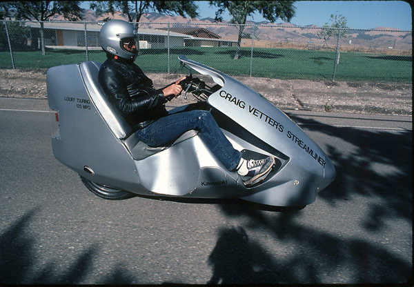
There isn't enough demand for Zero to produce a Vetter style of slipstreamer, but they mention adding 30% more range to their current models with well-designed fairings, and that number is spot-on. I am excited to see they are already getting 180-miles per full charge, and 30% would be 230-miles.

When I was young, I recall occasionally riding motorcycles from Los Angeles to San Diego and back, roughly 100 miles each way, and at the end of the 1.5 hours on a moto seat, I was VERY ready to find a restaurant and a couple beers with a view of the beach...the 10-hour full recharge would mean I'd have only needed 6 hours of charging to be full again, but at a 40% SOC, I'd only need a two hours of charging to be certain of getting back home...

Speaking of Aero, here is Craig Vetter in his attempt at designing a practical high-mileage transport:

1981-Streamliner-at-speed.jpg
 
Lebowski said:
flathill said:
Zero needs to throw the sevcons in the dumpster and build their own controller with a built in charger.

I agree and they should buy my controller technology :mrgreen:

Seriously!!!
 
So why not go up to a higher voltage that would work with the existing charging infrastructure? "If we went to 300 volts, it would hurt you on every front that matters," says Zero's Senior Battery Specialist Luke Workman. "We'd have lower efficiency, lower power, higher cost, higher drive train heat – and in terms of life safety for the guys that are working on these things, you go from a nasty tickle … to dead. "

Lower efficiency? Lower Power? Higher drive train heat? Are you sure? None of these statements are true if you spec the motor and controller accordingly. Cost - OK I concede there will be a price rise for higher rated parts, but it's not that much. Safety is simply a matter of designing it right, but I can see that the current modular pack system would no longer work as nicely.

If controller technology doesn't improve to a point where you can get 100 kW from a 100 volt battery with good efficiency (and at 1000 amps, that's quite a challenge) then I can only see voltages rising in the near future. 700 V is probably too much for a road going bike, but 360 V max is spot on for a race rep machine.
 
There are very real and difficult design challenges of controller power stages after crossing the 500A range. The design must be very robust. I have not seen any "good" designs which are commercially available, but I haven't seen everything. I'd like to see the controllers used in the fast NEDRA racing bikes/cars.

I believe there is going to be a very large market for reliable inverter tech over the next 5 years. I don't see many trying to meet this challenge.

One of my friends is working on a micro power grid involving VFDs and they found only one that can do regen (quadrant 3) and handle 300kw with a 700v bus. That's over 400a. power stages are difficult to make live at this power level due to the amount of emi they generate. Just imagine what a cascading failure of the output silicon is like at this power level. The shrapnel could do some damage along with the plasma ball.

I believe there are advantages of low voltage high current as Luke has said, particularly with life safety, but it's going to require more people working towards that goal. I am trying to push limits with my own work.
 
Compared to a Sevcon (which is no gem) the Vf loss alone from an IGBT based system is greater than the total controller losses at peak power today.

Don't forget guys, it's only a self-imposed limitation to only be using 3 phases. It's not like it's hard to bring 6 or 9 or 12 wires out of a motor and make a controller that easily drives 500A into each one of them.

The fact stuff tries to do it all in only 3 phases and HV today is a legacy artifact of industry where motors often have hundreds thousands of feet of cabling between them. The moment your total battery to controller distance and controller to motor distance becomes just a few feet, growing conductor cross-scross-section and/or additional phases becomes the radically better choice when you look at the system level perspective. It's really a no brainer. The only reason to ever use insta-kill voltages is for applications where you have hundreds or thousands of feet between battery/motor/controller. If those components are packaged closely (as they almost always are on all EVs), the choice becomes obvious.
 
liveforphysics said:
Don't forget guys, it's only a self-imposed limitation to only be using 3 phases. It's not like it's hard to bring 6 or 9 or 12 wires out of a motor...

:mrgreen:

Please correct me if I'm wrong, but isn't there an inductance advantage of doing it on different teeth instead of just splitting the windings on the same teeth like I understand you guys have done in order to use 2 controllers? ie, for the same Kv you pick up increased mutual inductance of the extra turns on the same tooth instead split between more teeth. Do sine wave controllers not have issues driving low inductance motors like the trap controllers I'm forced to use?
 
liveforphysics said:
The only reason to ever use insta-kill voltages is for applications where you have hundreds or thousands of feet between battery/motor/controller. If those components are packaged closely (as they almost always are on all EVs), the choice becomes obvious.

If one wants to produce +300kw, higher voltage is very beneficial and it's easier (partly because everything is already designed for this). Don't forget about stuff like trains or other high power stuff like earth movers. High voltage is not bad, it's just different.

I'm not opposed to multi phase arrangements or multiple controllers. Running +6 phases opens up some pretty cool options beyond lower voltage. Controllers can incorporate more redundancy, the torque ripple at low RPM can be eliminated by opposing the force in other windings. Really cool stuff.
 
I have thought about building things like a 5 or 7 phase motor controller... from an algorithm point its relatively easy to build a sinewave FOC for this, the main difficulty is finding a chip with 5 or 7 complementary PWM output stages. A nice big FPGA would do the trick though...
 
HV is used today because just a few years ago, the only practical way to achieve high power was through leveraging IGBTs designed for industrial motor control.

MOSFET power density continues to grow by significant steps regularly. A few feet of aluminum bus bar costs a few dollars.

Even if MOSFETs never improved again over what is available today, HV systems be looked back on and laughed about once EV traction designs mature a bit.

Doing what makes sense for reducing cabling costs on some distantly mounted industrial factory equipment is preposterously illogical when you only need to transfer energy a few feet. $5 of aluminum bus bar can replace $100's of dollars of BMS cost and complexity, not to mention the IGBT Vf efficency hit and needless safety hassles and life safety issues.
 
Once the 3 terminal triode type battery cells that have integrated switching (ion or whatever flow control separator) we may even see systems that are only a few volts with all the cells in parallel. It has been done before by Ford in the 70s. Perfect when paired with totally silent drive homopolar motors with true direct torque control (AC motors will never have pure direct torque control, you can come close though). Ford was using 1.5V max. We will be looking at using 5V max. Just like the controller is now integrated and direct mounted to the motor in any good EV design, so too the battery will be in the future. That is my prediction anyway.

Right now ~100V is the sweet spot. This may go up a bit with SiC JFET's though. SiC JFET's can be paralleled super easy, as many as you want. Still I would rather have a 100V bike I can work on myself and ride through a river. We are at the point where everything is good enough besides the batteries. Now the trick is total integration. There is no need to risk safety for another couple dollars of saving or to gain 0.5% efficiency. Cell energy density has already doubled from what is on the market today, with much longer cycle life, better low temp performance, and longer life at high temp. This is what the OEMs have been waiting for. The transition to electric drive is going to happen much faster than you might think. Zero has first mover advantage, but it will all be for nothing they don't become more radical. Maybe the plan is just to sell out, but I would rather them become the Telsa of motorcycles, made and engineered in the USA. A revival of the American motorcycle industry.
 
flathill said:
SiC JFET's can be paralleled super easy, as many as you want.

Why is a SiC JEFT easier to parallel than any other type? There is still the issue of current sharing during the switch on/off events. SiC is nice because it can have lower switching losses and that can allow it to switch at higher frequency. High Fsw has it's own issues though like LF distortion created by the dead time since you get less dead time overhead as Fsw goes up.

In the end it's still a balancing act when building a drive system. Everything has its place.
 
You are right careful design is still needed at higher frequency, but compared to SiC MOSFETs with a negative coefficient of on-resistance, SiC JFETs inherently have a very high positive temp coefficient so they parallel rather well. Motor controllers don't need much more than 20-40khz unless you are driving an ironless motor. SiC MOSFETs also need custom gate drivers (20V+swing) while SiC JFETs can use off the shelf stuff.
 
flathill said:
SiC MOSFETs also need custom gate drivers (20V+swing) while SiC JFETs can use off the shelf stuff.

Aren't SiC JFETs normally on?

I've got some Cree C2M0080120D for a project I'm working on, nothing special required to drive them. They do have a high Vf ~4V, but will be used on a 400V bus. I've seen some hybrid IGBTs that use a SiC diode which only has a 1.6V Vf and the rest is Si.

SiC MOSFETs have a positive temperature coefficient, the C2M0080120Ds I have are pretty easy to drive and I don't see anything unusual with driving them.

One of the big benefits of SiC devices they have a much higher operating voltage range. It's going to be a little while before the devices are affordable though, $16ea. Right now SiC and GaN devices are priced like blue and white LEDs were when they became available.
 
Looking at figure 4 on your device datasheet it does appear it has a postive temp coef. This is because they only normalized the 20V data set

But note in figure 6 that the temp coef at 14,16,and 18V is actually negative before it turns positive at higher temp

This causes temperature instability. Channel mobility increases in a sic mosfet with increasing temp it is just that above a certain temp channel resistance is no longer dominating the on resistance. If you look at sic jfets the temp coef is positive at all temps no matter the gate voltage. Both sic mosfets and jfets are very good now in any case as the thermal stability has been improved to a point where it is not an issue in most apps
 
Cool
 
Back
Top