RC Mid drive project - trial/freeride style

Stielz

100 W
Joined
May 20, 2011
Messages
211
Location
Wellington, New Zealand
Just in the planning stages of my next project.

Im going for a high torque machine rather than outright speed, I want something that can go up really steep tracks and stairs, pull continuous power wheelies right up to 50km/h, all the good stuff like that.
Im thinking I will most likely use an RC motor because of their high power density - small and lightweight compared to hub motors.

After many many hours of browsing this forum I have been inspired by many builds - to name a few:

Ratkings downhill/freeride bike http://endless-sphere.com/forums/viewtopic.php?f=28&t=22692

Timma2500's build http://endless-sphere.com/forums/viewtopic.php?f=28&t=45438

panurge's build http://endless-sphere.com/forums/viewtopic.php?f=28&t=25101&start=50

dustyearlobe's dual cyclone build http://endless-sphere.com/forums/viewtopic.php?f=28&t=42580

recumpence's sick dual astro build http://endless-sphere.com/forums/viewtopic.php?f=28&t=9534

and of corse liveforphysics' twin C80100 http://endless-sphere.com/forums/viewtopic.php?f=28&t=8347


Also i should mention that I am building an EV motor controller as part of a masters project, Im a optimist and am hoping that in about a year or so I might have made a controller that can handle these hard to drive RC motors.

Im currently just keeping an eye out for second hand bikes that will fit my criteria for this build.

Something ive been working on in the meantime is putting together a spreadsheet of potential motors for the project. Ive been scouring the internet for specifications of some suitable RC motors and adding to the spreadsheet all information I find like Kv constant, current, voltage, power rating, phase resistance, inductance, no load current, weight, size, etc. I can then enter things like batt voltage, wheel diameter, gear ratio. The spreadsheet performs a bunch of calculations and gives estimated maximum wheel torque and speed. I think this will be a very useful tool in designing for this build.

I will make this spreadsheet public when its a bit more complete, I still have alot of missing information at the moment.
Just wondering, does any such spreadsheet exist already? Any input will be appreciated, I know some people have done testing on motors to find out this information.

It would be nice if we can create some master spread sheet so we can get a full list of specs of all the motors that people on this forum like to use. I know how frustrating it is when the sellers of the motors dont give you all information about the motor.
 
Looking forward to see what you come up with. You'll be the 2nd Kiwi to take on an ambitious custom RC capable controller. Everything went quiet with 'RickyNZ' after many years of development work. Give him a prod if you run into him :lol:

Re. spreadsheet. I think the most useful parameter to gauge the desirability of different motors is torque per unit weight (both burst and continuous with the feasibility and incorporated weight of cooling options being considered). All the other parameters can be manipulated to an extent, but to my mind this is the single most important parameter in ranking potential BLDC motors. Search posts by 'Miles' on this in particular.

As an example of why the incorporation of cooling systems is so important, 'toolman2' is measuring 20Nm continuous/30Nm burst from a CA-120-70 with a high pressure leaf blower out of a 2.4Kg motor, effectively doubling the motors capability from just passive cooling. The leaf blower motor and ducting doesn't add that much weight and so the motor mightn't look so fantastic based on published specs with passive cooling....Being an out-runner, it's also much easier to air-cool the coils than most in-runners.
 
Stielz said:
Something ive been working on in the meantime is putting together a spreadsheet of potential motors for the project................................

It would be nice if we can create some master spread sheet so we can get a full list of specs of all the motors that people on this forum like to use. I know how frustrating it is when the sellers of the motors dont give you all information about the motor.
Good idea. This thread might help: http://endless-sphere.com/forums/viewtopic.php?f=30&t=45489.

Also, it might be useful to incorporate this spreadsheet:
http://endless-sphere.com/forums/viewtopic.php?p=312555#p312555
 
The GNG motor would be perfect for what you want, it is a amazing motor for the price. It kicks ass on high voltage. In this video I run 14s 70A but 24s 45A works even better !
http://www.youtube.com/watch?v=dLpr9aSfHvE
 
I don't understand inductance, but I have read that RC motors have a lot of it. RC motors that function well on a model airplane have often killed their ESC in a quick and fiery death on E-bikes due to high sustained loads on acceleration, when they normally would have accelerated rapidly up to high RPM's if used in their design application on a model plane.

The "go to" RC ESC is a Castle HV-160 with added input low-ESR capacitors. Or, you can add hall sensors to an RC motor, which allows you to use a common E-bike controller, such as the popular Lyen 6-FET/ 12-FET...

If the 4-1/2 inch diameter GNG motor interests you, here is an index of GNG builds: http://endless-sphere.com/forums/viewtopic.php?f=28&t=42785#p625237
 
Looking forward to see what you come up with. You'll be the 2nd Kiwi to take on an ambitious custom RC capable controller. Everything went quiet with 'RickyNZ' after many years of development work. Give him a prod if you run into him :lol:

Re. spreadsheet. I think the most useful parameter to gauge the desirability of different motors is torque per unit weight (both burst and continuous with the feasibility and incorporated weight of cooling options being considered). All the other parameters can be manipulated to an extent, but to my mind this is the single most important parameter in ranking potential BLDC motors. Search posts by 'Miles' on this in particular.

As an example of why the incorporation of cooling systems is so important, 'toolman2' is measuring 20Nm continuous/30Nm burst from a CA-120-70 with a high pressure leaf blower out of a 2.4Kg motor, effectively doubling the motors capability from just passive cooling. The leaf blower motor and ducting doesn't add that much weight and so the motor mightn't look so fantastic based on published specs with passive cooling....Being an out-runner, it's also much easier to air-cool the coils than most in-runners.

Wow thats alot of torque, he must be pushing some serious current through that!

And thanks for the link Miles, that filled in a few bits of missing information for me and I've added some more calculations to my spreadsheet for Motor Constant [Nm/√W] and Specific motor constant [(Nm/√W)/kg]

bzhwindtalker, thats an awesome video, thats alot like what Im going for with this build.I never knew you could get that performance from those GNG motors!

Anyway, regarding the motors inductance, I always thought that RC motors had really low inductance.. this is what makes them a nightmare to drive. The electrical time constant for a DC motor is given by Tm = Lm / Rm so with low inductance the current is able to increase at an exceptionally fast rate. Even with the standard 20ish kHz PWM frequency at low duty cycle, the on-time of the FETS is enough for the current to exceed the FET current rating and destroy them
 
So my plans for the bike,

Im thinking I will be driving the wheel through a seperate chain to the pedal chain. Dont really want to have to be moving the pedals all of the time while motoring.

I do like the idea of using an internal geared hub for the pedaling side of things and just having a single speed chain drive from the pedals. I have heard that the Nu Vinci Hub is very good but also heavy. Although I don't think I have the need for a continusly variable transmission. For my requirements I'll probably be happy with a 3 speed internal geared hub which are alot cheaper. Has anyone tried the cheap Shamano 3 speed hub from Amazon? almost seems too cheap to be any good.

http://www.amazon.com/gp/product/B0..._m=ATVPDKIKX0DER&pf_rd_r=06J3ZMKYS40Y3HFJTKSK

As for batteries, I have 8 x 5Ah,5S lipos that are in my current bike, running as 20S 2P. The only issuse I have with this is charging them, I have to disconnect every battery and plug them into a parallel charging harness and charge them as 5S with my turnigy mega 400W x 2 charger. Just is a bit of a hassle. Dont really want to move on to a high voltage charger with no cell balancing because I dont want to have to use a BMS.

Maybe a solution would be to build a bike that uses 10S lipo because there are some high power 10S balance chargers available and so that would mean not having to change the battery configuration from series to parallel for charging.

But of corse at 10S I wont be running those big outrunner motors at their full potential. So its a question of whether its worth the trade off. Probably not lol
 
Some initial thoughts on the drive terrain, I have narrowed down to two options that I think will be best:

A) Have the motor(s) mounted within the frame of the bike, have a two stage reduction drive to the wheel. Using a sprocket mounted off the pivot point of the rear suspension would be ideal, removes the need for tensioners. Only problem is that there are very few frames that will allow for this, so I am looking for one that has a single pivot rear suspension and has the pivot located such that a sprocket could be mounted there and be clear of the pedal cranks. May be an option to extend the pedal cranks outwards to give more space. And also the chain must be able to access the rear wheel sprocket without interfering with the swing arm.

B) Extend the rear wheel back so that there is space for a motor just in front of the wheel, mounted on the swing arm, single stage gear reduction to the wheel. This way will need either a low Kv motor (70kv or so) or lower voltage (10S lipo or so) to get the right gearing as I wont be able to get a lower gear ratio than 10:1 in a single stage reduction.

An avanti D8 appeared on trademe recently which looks like it may be a candidate for option A.

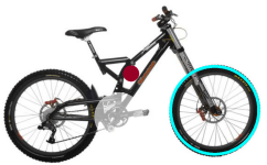
Using autoCAD I scaled the image to be "actual size" using the 26" wheel as a reference so that I can draw motors and sprockets in actual size and see if they will fit.

It looks like the 120mm diameter motors wont fit within the frame

Capture1.PNG

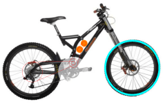
However the 80mm diameter motors will. Two of them in fact :D Also it has single pivot suspension and the pivot is in an accessible place (on the side without the pedal sprocket)

Capture.PNG

The thing I like about this bike is that the seat assembly is bolted on so can easily be removed or I could make a modified version that has the seat much lower, that will make it more like a trials style bike except with mad suspension.
 
don't get hung up on the 2 motor idea ( dont get me wrong it works perfect :twisted: ) but on something that is as light as a bicycle it will really not be necessary. If you are going to use the 80mm outrunner then think about re-winding as this can make them run so much cooler and slower, also to make these motors really work well with a 12fet controller is to use external hall sensors ( not internal ! ) . You could use 63mm motors if you want to use 2 motors and use 6fet controllers no re-wind is nessersary ( external hall sensors are needed ) but these may be a little fast (180Kv).
 
you can re-terminate the RC motors from Delta to WYE http://endless-sphere.com/forums/viewtopic.php?f=30&t=36767

spinningmagnets said:
The "go to" RC ESC is a Castle HV-160 with added input ESR capacitors. Or, you can add hall sensors to an RC motor, which allows you to use a common E-bike controller, such as the popular Lyen 6-FET/ 12-FET...
I disagree, have no personal experience with the Castle HV-160, but with other ESCs. They just suck if compared with X8M06 controllers. Heard that Lyens have problems with low inductance/RC motors. Never tried that, just way too expensive. Always hear that people have problems with these.

The 8085-8T runs at ~100KV in WYE with enough phase inductance. If you stay below 5700rpm, you can run such a motor with the sensorless bmsbattery/greentime/X8M06 series controllers quite smoothly. Tried that with the 80-100 . Sensors never did a good job for me, just dislike them since they fail eventually. The effort of mounting them is in vain IMO. Such a 12Fet sensorless with 3077 FETs @ 48V / 50amps is a feasible combo that I thought about a lot. Just too many projects ATM, maybe next year.

Two motors make a lot of sense. But I would go for only one first, then upgrade. I would place the motors below the downtube if you dont need that space for batteries. Option B is even more sexy... the lower COG the better.

Good luck with your built, keep us postet!
 
Thanks crossbreak, I have an EMP C80100-130 which I tried re-terminating to wye for another project but wasnt able to separate the phase ends because of how much epoxy glue the motor had holding the wires in place.. did you have any problems with excessive glue when you re-terminated yours?
 
Its been awhile since I posted anything here, just been too busy so haven't been able to make any real progress on the bike.

I have however brought a bike for the conversion. Its a 2004 Giant DH Team which I brought on trade me for only $500 NZD. Seems to be in pretty good nick, just a few maintenance issues, the rear suspension is bouncy and the the brakes are quite squishy even after a bleed.. maybe needs replacement seals or something?

Also I don't much like the colour, will be giving it a respray.

 
Stielz said:
As for batteries, I have 8 x 5Ah,5S lipos that are in my current bike, running as 20S 2P. The only issuse I have with this is charging them, I have to disconnect every battery and plug them into a parallel charging harness and charge them as 5S with my turnigy mega 400W x 2 charger. Just is a bit of a hassle. Dont really want to move on to a high voltage charger with no cell balancing because I dont want to have to use a BMS...

Do some more research on here.
Constant balance charging is not "essential" for multi cell lipo packs, and a BMS is certainly not necessary even without balance charging.
Cell "monitoring" ( cellogs or such like) and attention when bulk charging, is the simple way to go .
Just keep within the accepted cell voltage limits ( 3.6 -4.2v )
I have a set of 10s, 3p lipo bricks that are several ( 4?) years old. I bulk charge daily and check after charging. I have not needed to balance any of them for over 6 months, and when i do it will most likely be a single weak cell that needs a 15 min boost to bring it up to the same voltage as the rest.
 
thanks for the tip, I have always been very careful with lipo batteries because of the fire danger but I see where youre coming from with just needing to keep an eye on the cell voltages.
 
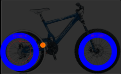
Here's a quick sketch of what im planning to do with it, just to get an idea of where things are going to sit.

Capture.PNG

Thinking I might go for a 17" moto rim and tire laced into a bike hub. Would like to use one of the old NuVinci hubs, the development kits seem to be going for pretty cheap. I reckon it would be pretty sweet to have it automatically always in a suitable gear for pedaling. http://www.utahtrikes.com/PRODINFO-Nuvinci_Developer_Kit.html

This hub however will require a dropout adapter. The drawing above shows where the wheel will sit with a 60mm extended wheelbase via custom made dropout adapters, which allows the 80mm diameter motor to sit nicely within the swing arm.
 
Not sure if what you have colored in blue is supposed to be the outer diameter of the tire for the 17 moto rim. I think if you go with something like a 3 inch wide tire on that 17 inch MC rim it will be almost as large in diameter as the stock MB tires you have on the bike now. I am not sure about this however.
 
the giant is the perfekt bike for a conversion. Why do you want to change the wheels to Motorcycle? They are much more heavy. I would only change the rear wheel. Have a look at the FX-Bikes, the have a strong and lite setup, running 18HP 4stroke Honda engines. Even they use MTB front wheels.

I would also recomend to put the motor under the downtube. It should be in the main frame, not in the swingarm otherwise the moment of inertia is to high and the suspension wont be smooth.
 
The blue coloured circle is supposed to represent the 80/100R17 tire. the way I got this is by adding 80mm x 2 to the 17" diameter rim.. not sure if that is completely accurate though.

I would also recomend to put the motor under the downtube. It should be in the main frame, not in the swingarm otherwise the moment of inertia is to high and the suspension wont be smooth.

I agree that ideally the motor would be mounted on the frame. The only reason I dont want to go for that is the added complexity in building the thing.

Also I don't believe the inertia it will add will be too bad. Its a 1.8kg motor right up close to the pivot point so the amount of movement it experiences will be small. Especially when we compare it to a 10kg hub motor centered right at the end of the swing arm.
 
having the motor in the swingarm is not a big issue and will not effect the suspension or handeling of a bike when the motor is that close to the pivot and it helps even more when using a light motor.
 
New paint job.

Maybe this shouldn't have been the first thing I do to the bike but just decided to do it while I figure out how Im going to do the conversion.

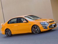
The colour is called Octane, the same colour as the Ford Falcon FPV.. Come out quite nicely I think.

View attachment 1
2008-Ford-Australia-FPV-F6-01-1024.jpg
 
Now back to the important stuff, for the power transmission I'll probably go for an 06B chain which is about the same as a #35 ANSI chain. Reason for this is I have the chain already left over from a previous project and its a reasonably fine pitch chain that will be strong enough for when I upgrade to having two of the C80100 Outrunners.

So the rear sprocket will be pretty large for a single stage reduction. Probably need to go for 114T or 96T which have diameters of 345mm and 291mm respectively.

A thought that crossed my mind is that it would be a nice setup to have this sprocket rim mounted. Could save on weight and complexity. Does anyone know of examples where this has been done before?
 
wheel chairs have rings for the hands. They are rim mounted.
A3_SPC_detail_04_640x480.JPG

A3_SPC_detail_01_640x480.JPG
 
Thanks crossbreak, that's exactly the sort of thing I was thinking. It should be possible to make something that's strong enough but will probably need to weld the mounting brackets onto the rim.. I think some Solidworks modelling is on order
 
will be quite hard to center it right. It's likely that the sprocket will wobble if the sprocket mounts that engage into the rim are not perfectly machined.
Machining a 50mm BCD sprocket interface into a normal MTB hub is the route I'd like to try http://endless-sphere.com/forums/viewtopic.php?f=28&t=56268. Elongating the swing arm (custom dropouts) and installing a 24" wheel clears the space for motor and gearbox.
 
Back
Top