RC Mid drive project - trial/freeride style

i did look very close..
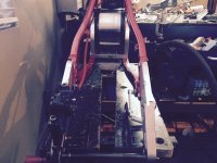
the adapter slides onto the freehub body..
the motor chain ring attaches to the adapter..
the motor chain ring is not fixed to the hub shell in this case but the freehub..
motor power to the chain ring is therefore run through the freehub paws..
freehub will not last long with this configuration under motor power..
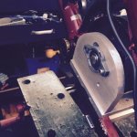
bzhwindtalker said:
efMX Trials Electric Freeride said:
once you send any significant motor power through the freehub it will soon break..
(first the engagement pawls then next the freehub mount bolt..)
bicycle freehub is not designed to handle motor power..
Look closer :)
I like this design
 
I don't think the motor chain ring attaches to the adapter, I think he's gone to a lot of trouble NOT to do that. If you look REAALLLYY close you'll see the motor sprocket bolts straight to the hub body, as per a brake rotor, and the modded cassette can do whatever the hell it likes in the centre of all that
 
ok i see it now.. thanks:)
2015%2B-%2B1

the hub flange is taped and drilled.. the chain ring adapter is bolted there..
the freehub rotates inside and free of the chain ring adapter..
nice setup.. but i would recommend a custom made hub for this..
taping and drilling the hub flange has reduced its engineered strength..
and now you will add additional stress with motor power..
not the strongest design for significant power without custom hub designed for task..
but i look forward to testing!

Ecobogan said:
I don't think the motor chain ring attaches to the adapter, I think he's gone to a lot of trouble NOT to do that. If you look REAALLLYY close you'll see the motor sprocket bolts straight to the hub body, as per a brake rotor, and the modded cassette can do whatever the hell it likes in the centre of all that
 
Stielz, what is your custom BCD on modified hub?

Looks like nine M3 bolts at around 48mm BCD?

If you can please also measure inner diameter of sprocket adapter that sits on hub.

Thanks a lot!
 
Your guess is close, its nine M4 bolts at 47mm center diameter.

Inner diameter of sprocket adapter is 40mm.

The sprocket adapter is just a machined down go-kart sprocket carrier. Machined a flat surface on the hub body, drilled and tapped threads to bolt the sprocket carrier direct to the hub body. Using go-kart sprockets and chain for this build.

efMX Trials Electric Freeride is right, the threaded holes have reduced the strength of the hub. How much though? I'm confident that it will take the force from the motor. We'll soon find out anyway
 
The DH Comp swing arm as two very convenient cross bars which I have bolted a 6mm aluminium plate across. I will use this plate to bolt the motor mount on to.

The motor mount is a piece of 4mm thick right angle aluminium with slotted holes to allow for chain tensioning. There is some flex in this part so I may need to find a thicker piece, we’ll see how it goes.

I still need to cut the motor shaft to length as the pedaling chain sits right in front of the shaft.

I then discovered that I won’t be able to fit the motor chain past that fat moto tyre. I knew it was a long shot but that tyre was practically given to me for free so no biggie.
Also the spoke length was a tiny bit too long so I wasn't able to dish the wheel as much as I wanted due to running out of thread on the spokes.

I have a new tyre and new set of spokes on the way for wheel building part 2.


2015%2B-%2B1


2015%2B-%2B1


2015%2B-%2B1
 
Yep time for an update.

The set of shorter spokes finally arrived so I was able to rebuild the rear wheel. I’m pleased I did have to rebuild cause it came out a lot better the second time around.

With the shorter spokes I was able to get a bigger offset for the rim, and with a narrower tyre I was able to get the clearance I needed to get both chains through the swingarm with no idler sprockets or rollers required for guiding the chain. That being said, there are some pretty small clearances between the motor chain and tyre, and motor chain and swingarm bars.

2015%2B-%2B1


2015%2B-%2B2


2015%2B-%2B3


2015%2B-%2B4


An interesting note on the tyre sizes. The new tyre size is 90/90-19 (original was 3.5” x 19). Converting inches to mm the new tyre should be slightly wider but that’s not the case - it’s around 5mm narrower. Maybe just down to the tread type..

Because of the 100mm extension of the swingarm, a longer pedal chain was needed. It ended up needing a 124 link chain which I made by adding an extra 8 links to a 116 link standard bike chain.

The 13T motor drive sprocket and 96T driven sprocket give a gear ratio of 1 : 7.38.

The motor is an stock C80100 130kv (for now) so looking at a no load wheel speed of 92km/h (maybe get 80km/h on a flat road?) with 12S lipo battery pack.

The plan has always been to re-wind the motor, aiming for around 80kv speed constant, and run on 16S lipo battery. That would give 75km/h no load (maybe 70km/h on a flat?).

So I reckon I’ll try it out with the stock wound motor on 12S battery first, just thinking it would be quite hard on the motor controller. BTW the motor controller is an Alien EV ESC, 300A, 4-24S, Sensored
http://alienpowersystem.com/shop/esc/alien-300a-4-24s-evolution-3-esc-hv-sensored/
 
Very nice built. Nice to see more wing-harm built.
I think your setup is great but it wont work without a bearing in the back
for support. the whole thing will bent.
like this


just my two cents...
but else everything look great!
 

Attachments

  • IMG_5.3.2015_163730.jpg
    IMG_5.3.2015_163730.jpg
    72.9 KB · Views: 4,698
  • IMG_5.3.2015_163833.jpg
    IMG_5.3.2015_163833.jpg
    54.8 KB · Views: 4,698
Do you have good acceleration with this transmission ? (13t - 96t) because with a motor @ 130kv without belt drive reduction i was wondering if it wasn't hard to push up a great acceleration :)

I want to do the same but i'm question me if i must do a drive reduction or not .. It's for a 18kW motor :p

Thanks :)
 
Very nice built. Nice to see more wing-harm built.
I think your setup is great but it wont work without a bearing in the back
for support. the whole thing will bent.

Definitely will check this out one I get it running, see just how much deflection there is in the motor mount under load (use the brake to apply a load). Hopefully it will be just a small amount and not a problem. Otherwise i'll try a thicker motor mount bracket.. would be difficult to support the motor at both ends with the limited space I have.

Do you have good acceleration with this transmission ? (13t - 96t) because with a motor @ 130kv without belt drive reduction i was wondering if it wasn't hard to push up a great acceleration :)

I want to do the same but i'm question me if i must do a drive reduction or not .. It's for a 18kW motor :p

Thanks :)

I'll let you know when I try it :D
Im thinking it probably wont be huge acceleration with 130kv stock wound motor.. But re-wind it to 80kv, thats going to get the torque constant higher - 0.12 Nm/A. Push 150A phase current through it thats 18Nm motor torque or 132Nm wheel torque which would be decent acceleration.

What speed constant is this 18kW motor? If its lower than 100kv or there abouts you should be able to get away with a direct drive setup. Just need a controller that can deal out the current and I'd definitely recommend a sensored controller
 
Thanks for your answer Stielz :)
For the motor it's the 18kw from Alienpowersystem, but they will send me another who have a 60Kv.. I will create a new thread about my project, i don't want to spam this beautiful thread :)

So, do you have update about your bike ? :) Need video fast as possible lol !
 
Im guessing its the 120-90? Should be a nice and overpowered bike :D
Check out this spreadsheet that I used to compare motor performance, gearing requirements, ect.
View attachment Motor Calculations.xls

The extended swingarm means more rear suspension travel and more leverage on the shock spring. It was feeling a bit soft with my original 550lb spring so I swapped it out for a 800lb titanium spring. Much better now

2015%2B-%2B1
 
Yes, that it ! ;) Bruno (from Alienpowersystem) told me they will receive a new 60kv motor ! It will be better for a direct drive :)

Thanks for this spreadsheet, there are very usefull informations and well updated !

Do you have tested the bike on road ?
 
Not operational yet, still a few things to go.

Currently finishing off the battery packs.
Still need to wire it all up.
Sort out a throttle. Going to use an Arduino Nano to convert 0-5V analog throttle signal to a PWM signal for the ESC.
Need to mount the ESC to the frame. Would like to 3D print some hangers for this but for now ill I'll just tape it to the frame.
 
Stielz said:
The extended swingarm means more rear suspension travel and more leverage on the shock spring. It was feeling a bit soft with my original 550lb spring so I swapped it out for a 800lb titanium spring. Much better now


Where did you score the Ti spring?
 
I didn't see which controller you will be using. For this motor, add four of the low-ESR capacitors to the ESC inputs. Many ESCs have died to discover this need: http://endless-sphere.com/forums/viewtopic.php?f=30&t=22194&hilit=nichicon&start=25#p382837

The gold part of the RC motor that mounts to the base-plate will get hot, so if you ever modify the mounting plate in the future, it is beneficial to use a thicker aluminum in that spot as a heat-sink. I would also recommend researching a centrifugal fan by Thud and recumpense to pull air through it. Like this:

http://www.endless-sphere.com/forums/viewtopic.php?f=30&t=54415#p810747

file.php
 
Where did you score the Ti spring?

By chance it popped up on Trade Me (NZ equivalent of Ebay) for $60 NZD only slightly used which seemed like a steal to me so I grabbed it before anyone else could
 
I didn't see which controller you will be using. For this motor, add four of the low-ESR capacitors to the ESC inputs. Many ESCs have died to discover this need: http://endless-sphere.com/forums/viewto ... 25#p382837

The gold part of the RC motor that mounts to the base-plate will get hot, so if you ever modify the mounting plate in the future, it is beneficial to use a thicker aluminum in that spot as a heat-sink. I would also recommend researching a centrifugal fan by Thud and recumpense to pull air through it. Like this:

http://www.endless-sphere.com/forums/viewtopic.php?f=30&t=54415#p810747

Good advice. The controller is Alien 300A 24S http://alienpowersystem.com/shop/esc/alien-300a-4-24s-evolution-3-esc-hv-sensored/
Because its a sensored ESC i'm hoping it will be more robust that the typical RC ESCs.

The Alien ESC has 5 large caps but they don't appear to be low ESR.. Maybe I should add some extra caps, low ESR for good luck.

Also I figured I'm not running near the max voltage the ESC can take - 16S with a 24S ESC. So there is plenty of headroom for voltage spikes.

Do you have experience using a centrifugal fan with this type of motor? I'm just a bit skeptical about how effective it would be with very limited openings for air flow in through the other end of the motor.

I like the idea of using the motor mount as a heatsink though, like what Luke did with his twin C80100 ebike and using CPU fans for extra cooling:

http://endless-sphere.com/forums/viewtopic.php?f=28&t=8347&start=200
 
Nobody has been able to clearly identify all of the culprits when an ESC dies. The voltage ripple was suppressed by adding more input capacitors (always low-ESR), and that helped. running 16S on a 24S max ESC should also help. Its my understanding that a problem with these motors is inductance. I can't properly explain it yet, and I don't know why its a problem. Thud has rewired this family of motors with a WYE termination on the phases, and that was apparently something that helped, but he also did plenty of experiments with adding sensors so he could run a more robust and less expensive E-bike controller.

Since you've indicated this ESC is sensored, just add halls to the motor and this should be an interesting project.

As far as the centrifugal fans go, they will help, but...they might not be necessary. If this was a bottom-bracket drive that gave the motor the use of the bikes gears (much lower peak amp-draws), I would say the fan is absolutely not needed, but...since it is driving the rear wheel, I suspect it will be something that's worth keeping in mind if the final product seems to be running too warm. Only time will tell, best of luck...
 
I've done some research on this topic previously when I built my own controller and was having issues with it blowing transistors.

Anyway glad you brought this to my attention. Lets try to put some real numbers to it.

Ripple voltage is highest at 50% duty cycle. The formula for voltage ripple @50% duty is Vrip = Vbus / (32* L * C * f^2)
Can’t remember where I got this from but a quick google search verifies it.
Using Vbus = 44.4V, L=39uH (apparently thats the inductance of a stock C80100 130kv), f=16kHz, we get this graph showing how much voltage ripple I can expect vs bus capacitance.

View attachment 1

This shows that we don't need a huge amount of bus capacitance - 100uF and we’re getting 1.3V ripple, or 3% of battery voltage.

The problem lies with ripple current. The formula for this is Irip = d * (1 - d) * (Vbus/(f * L))
Again probably should have referenced where I got this from
Using the same values for Vbus, f, and L, we get this graph showing expected ripple current vs duty cycle.

View attachment 2

This shows that I should be expecting ripple current of 17.5A max. Using aluminium electrolytic low ESR caps, that calls for quite a few of them to get the ripple current rating. Maybe could use some film caps as well for their high ripple current rating.

So my understanding is this: the inductance of the motor winding quantifies its ability to “resist” or “slow” the rate of change in current through the winding. So a high inductance winding will cause less ripple current than that of a low inductance winding, and so a high inductance motor will not need as many bus capacitors, assuming the capacitors ripple current rating is the limiting factor.


Regarding hall sensors for the motor, already got this from the motors previous life in my motorised mountainboard (which didn’t get used anymore because I built a better electric longboard). Its got two sets of hall sensors, one set positioned for neutral timing and the other positioned for 30 degree advanced timing.

IMG_0754.jpg
 

Attachments

  • Irip vs DC.PNG
    Irip vs DC.PNG
    6.3 KB · Views: 4,364
  • Vrip vs Cap.PNG
    Vrip vs Cap.PNG
    5.8 KB · Views: 4,364
Stielz said:
I didn't see which controller you will be using. For this motor, add four of the low-ESR capacitors to the ESC inputs. Many ESCs have died to discover this need: http://endless-sphere.com/forums/viewto ... 25#p382837

The gold part of the RC motor that mounts to the base-plate will get hot, so if you ever modify the mounting plate in the future, it is beneficial to use a thicker aluminum in that spot as a heat-sink. I would also recommend researching a centrifugal fan by Thud and recumpense to pull air through it. Like this:

http://www.endless-sphere.com/forums/viewtopic.php?f=30&t=54415#p810747

Good advice. The controller is Alien 300A 24S http://alienpowersystem.com/shop/esc/alien-300a-4-24s-evolution-3-esc-hv-sensored/
Because its a sensored ESC i'm hoping it will be more robust that the typical RC ESCs.

The Alien ESC has 5 large caps but they don't appear to be low ESR.. Maybe I should add some extra caps, low ESR for good luck.

Also I figured I'm not running near the max voltage the ESC can take - 16S with a 24S ESC. So there is plenty of headroom for voltage spikes.

Do you have experience using a centrifugal fan with this type of motor? I'm just a bit skeptical about how effective it would be with very limited openings for air flow in through the other end of the motor.

I like the idea of using the motor mount as a heatsink though, like what Luke did with his twin C80100 ebike and using CPU fans for extra cooling:

http://endless-sphere.com/forums/viewtopic.php?f=28&t=8347&start=200

The fan you see on the C80100 is installed on my bike. The cooling results were better than expected, greater than 20 C reduction on a specific ride. See http://endless-sphere.com/forums/viewtopic.php?f=30&t=44287 for more data and graphs on the motor and the cooling provided by the centrifugal fan. I like your build BTW.
 
Thats good to know, I'll keep that in mind after seeing how the re-wound motor performs.

Im thinking i'll go for a single strand 14 AWG 12 turns DLRK. Take all 6 wire ends out of the motor so I can change between star and delta (55kv and 88kv).

Or maybe 13T of 14 AWG if I can fit it in.
 
Back
Top