24s BestechPower BMS Thread

izeman said:
are you sure that the bms was the cause for the dead cell? afaik it should only pull a very very small current.
where the cells charged to storage voltage before winter, or was it empty already?
I am positive as that was the only thing attached, and all cells were perfectly balanced before. It had been probably at least a month though.
 
it would help if we knew which ones went dead. i think it is most likely that the shunt transistor is damaged and shorted so that it leaks down through the shunt resistor. you should be able to measure it with your ammeter. the circuit current is about 20uA. you can calculate how long it takes to drain the cell. or the bottom three cells.
 
could it be that the controller was still attached? had that problem with a friend. he forgot to disconnect the controller and the battery had once cell go down to zero, where the other eleven were still around 2v.
but if really the bms drains down a single cell and discharges a at least half full cell within a month than this is a broken product.
i personally had no problem with this so far.
 
The controller wasn't attached, and, if a controller were attached, it should drain the cells evenly. It only drained one cell which was the cell attached to ground. All of the other 23 cells closer to the positive were barely drained (could easily be accounted for by self discharge).

I do not know id it is broken or if left for more than a month it can just kill the first cell.
 
i think the shunt transistor got shorted to something and is now shorted out. if you charge up that cell with a cell phone charger you can measure the current flowing over the sense wire with your voltmeter or just measure the voltage across the shunt resistor.
 
Got a chance to test it with my multimeter, and at least one of the discharge MOSFETs must be shorted, but I've never incorrectly connected any of the plugs, and I can't see any visible damage, so I'm not sure how it happened. Also, if I do choose to run 24s again, I am going to have to replace the cells as one was very puffy and I dont feel safe trying to revive them.

I'll probably try to pull discharge fets when I get a chance and see which ones blew.

Seeing as I'm not using the discharge plug, I'll probably just remove any that are shorted.


Any idea how to prevent this in the future, also, will the board work to manage 23s?
 
the mosfet would be next to the shunt resistor. it is not the output mosfet, it is the shunt transistor that i think is shorted.

someone else shorted the mosfet on channel one and we hacked it so he was able to bypass channel #1 but it has only 2 cells of voltage to run the circuitry so it is not safe that way.

you test it by charging up that dead cell on #1 to 4.2V, then put the ammeter in the sense wire so as the current drains out of the cell it will go through your ammeter. it should be about 170mA if the mosfet is shorted. that would drain the cell down in a few weeks. that is why i think this is the problem, not the circuit current.
 
The tiny little surface mount transistor labeled Q1 is also shorted which I'm presuming caused the shunt resistors for cell 1 to continuously drain the cell.
 

Attachments

  • IMG_20131120_154212.JPG
    IMG_20131120_154212.JPG
    203.8 KB · Views: 2,435
Do you or bestek provide any kind of warranty or support with these issues, and would such a warranty cover the damage to the batteries?
 
Q1 is the shunt transistor. that was what i have been talking about. if you disconnect the sense wires you can measure the body diode of the mosfet between the source leg and drain. since it is a p channel mosfet the bias is reversed. the drain will be forward biased to the source.
 
I know that that is what you were talking about, but I couldn't get to that until I took it apart. I could measure the fets ontop without doing that.

The shunt resistor, Q1 allows current flow either way between the legs that are on the same side of the package. What could have caused this issue and how can it be fixed?

Could the board simply be run with 23 cells and not use that channel.

Or, if the board, as I would suspect, requires the common ground there, can I transplant the transistor from channel 24 to channel 1 and use it with 23 cells that way?
 
how did you measure the resistance between the source and gate?

usually when the shunt transistor is shorted it also takes the gate driver/comparator with it.

if you can establish that the mosfet is bad by testing the body diode between the drain and source, or if the gate is shorted then you can swap it with the one on channel #24 or we can try to get another one.

if the mosfet is blown out then the comparator will need to be replaced too if it is bad.
 
dnmun said:
how did you measure the resistance between the source and gate?

usually when the shunt transistor is shorted it also takes the gate driver/comparator with it.

if you can establish that the mosfet is bad by testing the body diode between the drain and source, or if the gate is shorted then you can swap it with the one on channel #24 or we can try to get another one.

if the mosfet is blown out then the comparator will need to be replaced too if it is bad.

I used the continuity test on my multimeter, and both the shunt transistor, Q1, and the mosfets on top in the discharge section read effectively o ohms of resistance. I am guessing that it is likely not all of the discharge mosfets that are dead as I have never discharged through the bms, however, I will have to desolder them all and remove them at some point to be sure.
 
dnmun said:
i really do not know how you are testing these devices. if you forward bias the body diode it will conduct and appear shorted.

I am running the continuity setting on the multimeter (same as the resistance setting, but it beeps if it is near 0 ohms). I have tested both forward and reverse bias (just switched the leads), and it conducts both ways leading me to believe that the transistor (and mosfet tested in the same fashion) are shorted and that it is not just the diode conducting in one direction.
 
I removed the heatsinks to start puling fets to see which of the top discharge mosfets was shorted, and, what I found was a stripped screw and 20 fake irfb4115 mosfets which would probably explain the failure (at least of the discharge mosfet). Their labels are all smudged, and they are all stamped crooked...
 
since the mosfets are wired in parallel they will all show up as shorted if one is shorted. i find the easiest way to find the bad mosfet is to put my fingers on them while they are conducting current and the shorted one will heat up the most. cut the source legs on it and then retest with the diode tester.
 
dnmun said:
since the mosfets are wired in parallel they will all show up as shorted if one is shorted. i find the easiest way to find the bad mosfet is to put my fingers on them while they are conducting current and the shorted one will heat up the most. cut the source legs on it and then retest with the diode tester.

I know that they are all in parallel.
 
I used a small 5v power supply and attached the source and the drain, but then I decided to apply it between the source and the gate as that is where the short was as that would surely heat up (seeing as that was where the short was). Somehow, the problem seems to have fixed itself because there is no short between the source and the gate anymore, and connecting the power supply to source and gate turns on the MOSFETs and disconnecting it turns them off. So, somehow, the MOSFETs fixed themselves, or there was a bridge of something on the board somewhere that was knocked loose.

I'm glad that there is not another issue with the board, however, I never used that functionality anyways, and the transistor Q1 and possibly the comparator that drives it will need to be replaced.
 
When you purchased this from bestek, was there any warranty written or implied?

How should I go about getting it repaired or having replacement components sent?
 
i never even asked about a warranty but not sure how they could be responsible in any case since you have used it for a long time now. when i get some money i am gonna order some more of the D167s and try to get some of the shunt transistors then but if you unsolder the one on #24 you could place it on #1.

someone else also has a shorted shunt transistor and he also wants to repair it. it also shorted on channel #1, because it is on the end and that was where it made contact with the battery.

we hacked that one so it would work like i said, but it only has 2 cells of voltage for the circuit current and that is not enuff to be safe imo but you could try it if you wanna. i have some ideas of how to take the circuit current off the next cell up(#4) too. to get back to the 3 cells of voltage for the circuit current with the channel #1 bypassed.
 
It appears as if it would just be easiest to way to fix the problem would just be to remove Q1.

After that, it is a very simple hack to power the cutoff circuitry from cells 2-4 instead of 1-3.

Rewire the positive of three to the positive of four:
cell 4 positive.png

Then rewire the ground to the new one (from cell 2)
cell 2 negative.jpg
 
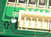
we did something like that but what you can do is solder those two sense wire pins together there where the solder pads are in your second picture.

that will bypass channel #1 and make the B1 pin become the new B- pin and it will then be connected to the B- spot up in the corner where the battery ground is soldered to the pcb.

for the circuit current voltage you can go look on the back side and see where there is a trace coming from the top of #3 and it runs over to the where the thermal breaker is soldered into the pcb. when you find that trace. look at it so you can grasp what it is that it does. the circuit current comes from the top of #3 and goes through that trace to the thermal breaker. from the thermal breaker it goes on to the gate drivers for the mosfets.

so when you bypass channel #1, the voltage that the circuitry uses is now only 2 cells high in voltage so at the LVC, that can be as low as 5.4V and that is too low to be safe for driving the mosfets.

so now you wanna go find the pad at the bottom of the shunt resistor for channel #5 since that will be the top of channel #4. it is easier to solder there to the bottom of the resistor, and you can see where the trace runs down to the B4 pin. that is where you wanna take off the circuit current for this new setup.

i did not see the wires for the 9 pin plugs i installed on that BMS in your picture either so you could solder the wire for the new circuit current there, except it is really hard to solder to them without shorting them.

but you still have the trace running from top of #3 over to the thermal breaker. if you unsolder the leg of the thermal breaker there, you can put a switch in the middle between the top of #4 and that wire to the thermal breaker, and the top of #3 is now no longer in contact with the thermal breaker since it is pulled out of the via.

so now you will have current from the top of #4 going through the switch, into the breaker and then it goes on to the mosfet drivers.

so now you will have a 23S BMS, but your sense wires are all now connected to the wrong cells. they will each have to be unsoldered and moved DOWN one cell, and the B- wire is now excess. so the top of channel #24 is now connected to the top of cell #23.

make sense? i would still like for you to verify that the Q1 is dead. instead of using the continuity tester, please use the diode tester function on your voltmeter to test the body diode of the shunt transistor mosfet. measure between the drain and the source, and show that it is shorted in both directions, compare the forward bias to the adjacent mosfet to prove it is defective. then test the gate to source with the diode tester by applying the probes to the gate and source and the gate and drain to prove it is shorted and how much in each direction.
 
Back
Top