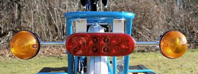
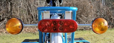
2WD Electric Yuba Mundo Build

MAN you must have a lot of free time!!! :lol: just kidding
Great work indeed. I love it,
I'm finding myself drawn to these bikes more and more.
I think it's time to look for an old Kona Ute maybe?
 
Misc Bits and Pieces...

Deflopilator

With the Mundo parked on the standalone kickstand, the front wheel is in the air and causes the fork to rotate around past 90 degrees until tension on the cables stops it. The Deflopilator is a spring that holds the fork and wheel aligned with the frame so the cables are not supporting them and the bike takes up less room.


The Deflopilator is a great little gadget but the added weight of the front motor thoroughly overwhelms it. The obvious fix is to upgrade the spring tension. A quick trip to Ace Hardware will get you a #175 spring and a 1.125” 8-hook (like an S-hook but closed). Attach the Deflopillator insert-screw-thingie to one loop of the 8-hook and the spring to the other. This combination yields proper tension, diameter, and length to restore proper operation and allows use of the original Deflopilator fixtures and plastic sleeve.

Rear Derailleur

After installing a DNP 11-32 freewheel , I needed to run down the derailleur B-tension quite a bit to get enough chain angle to shift reliably. The sprocket changes, an extra inside axle washer, and the hub motor got me into a bit of other rear derailleur adjustment. As it turns out, the BMC hub moves the spokes outward enough so that a pretty extreme Low setting is required to avoid hitting them with the derailleur cage – so far, in fact, that the High derailleur adjustment cannot work. The mechanical layout of the derailleur simply doesn’t allow sufficient adjustment latitude because of the placement of the screws and stops.

My cure was to stack two 1.5mm SS washers as spacers on the hanger to move the derailleur outward a bit. This moves the cage away from the hub and spokes requiring a much less extreme Low adjustment and so allows the High adjustment screw to align with its stop. Normal adjustment procedures now go easily.

In a recent exchange about this in another thread, neptronix pointed out that a freewheel spacer would do the trick. Looking at the geometry, I can see this will have the same effect as the hanger hack, but the clearance between the outer sprocket and dropout is minimal - it won't take too much spacer to push the freewheel out too far. So - it’s on my list of ToDo’s to investigate when the wheel comes out next time, but no real rush (“If it works, …”).

Chain Guide

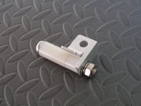
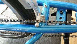
A side effect of the small 11 tooth sprocket is that if cross-shifted to the smallest front and rear sprockets, the long chain is so low that it sags and rides on the chain stay. Although this shift combination is a no-no and shouldn’t be used, I added a little nylon chain guide to lift the chain in that gear only, saving the paint when “shouldn’t” turns into “oops!”. It's made from a small piece of 1/16" aluminum angle and some nylon spacers from Ace Hardware.

As it turns out, the large chain ring is used exclusively and never shifted, making this questionable addition even more pointless. But I did it and have the pictures, so here you go... ;)

14-02opt.jpg
14-04opt.jpg
 
Balance Charger

At the beginning of the project I ran across a post by GGoodrum using some power strips to mount VoltPhreaks single cell chargers.

View attachment 1
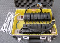
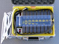
This was elegantly simple, solved fabrication problems, and sidestepped BMS issues. This became my model for a portable dual 8s balance charger.

11-12.jpg
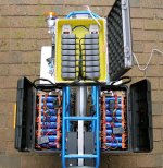
The case has some air circulation space that can also be used to pack some spare parts and larger tools for vacation traveling with the bike. The single cell chargers are from VoltPhreaks http://www.voltphreaks.com/, the 8 outlet power strips are from eBay, and the case is an Ape Case ACHC5500 from Amazon. The case was a little expensive, but it was the right size and had a much stronger handle than similar cases. The connectors are the male mating versions of the CN-36 connectors discussed in the Battery post. The chargers are a bit too wide for the socket spacing and it was necessary to sand the sides of each charger a bit so the chargers would seat properly in the outlet strip. Rivnuts are epoxied into the power strip mounting holes so they can be screwed down through the bottom of the case.

There’s not much to say – plug in the balance charger connectors and turn it on; all green LEDs means ‘fully charged’ ;) . Works sweet - perfect balance every charge, Headways are very happy - it's just pretty much an overnight affair...

11-04opt.jpg
Shortly after packaging this up, I noticed that the chargers were running hot and so stuck in an ad hoc fan and air deflector that pressurizes the central channel between the chargers and allows the air to escape by washing over the tops. This cooled the charger cases down nicely according to my precision fingermometer. The fan is an old derelict 3x3" from 'the fan box' (120vac PeeWee Boxer PWS2107FL, unknown CFM) that moves a lot of air but sounds like a 747. The deflector is fabbed from a 1/8x3.5" wide strip of scrap plexiglass.


11-20opt.jpg
Oops...

Unfortunately, I had missed some subsequent posts that discussed overheating issues with this scheme. In a recent thread oatnet gave me a heads-up. I contacted Tony at VoltPhreaks and he acknowledged the side-by-side overheating problem but thought that proper fan cooling would solve the issue. He reiterated the advice from oatnet that the preferred power strip mounting technique for passive cooling is to use every other socket.

I ordered a digital thermometer and thermocouples which arrived recently. The plan is to open a charger, instrument it with the temp probes, seal it back up, then run some test scenarios: separated, side-by-side, side-by-side with fan and enclosure as above. If the fan results are not satisfactory, I can run some additional tests with holes drilled for ventilation.

I continue to charge with the fan set up -- 40+ charge cycles and no issues yet, so I’m hopeful that the tests will indeed show the internal temps to be reasonable. More on this later.

Meanwhile, even though all seems to be working fine, until I get some actual test results:
DON'T PACKAGE VPHREAKS CHARGERS LIKE THIS! :(

EDIT - See new post with inexpensive modification for improved cooling.
 
wow! I'm just speechless cos everyone already said it for me

and imagine that... not a strip of duct tape anywhere 8) 8) 8) 8) 8)
 
Thanks Dee Jay, appreciated...

Pretty much caught up on the build to date - time to revisit the charger snafu, look into some parts upgrades, and finish up the battery part of the build... Warm weather's coming! :D
 
How did you get all those posts in one day? Awesome build man, very impressive utilitarian transport you have. I didn't read it all, but I'll go back and read the details. Thank you for sharing your experience with the forum.
 
Thanks, glad you enjoyed the read.

As for the post: I took all the pictures last year as each part was completed and I have a project notebook with the all the notes, wiring, etc, so I just had to bang out the tale - pretty easy. I drafted the posts on and off ahead of time and then just cut and pasted them into a new thread in one sitting. I've been meaning to do a thread for some time and with Spring, new builds, and new plans, I thought it was a good time to finally get it out there...
 
Parts Upgrades

Ride Fixies

If only someone made a FS cargo bike... but the Mundo isn’t. It seems my upgrades to date have been to plush up the ride: Fat Frank 2.35 tires, a SunLite Cloud 9 cruiser saddle, and a Thudbuster LT. There’s not much to say about the tires and saddle - big tires work and the saddle is a personal butt thing – both were good investments. But the coolest thing has been the Thudbuster – seriously – if you have a Mundo get one of these – the ride improvement is worth every penny. Since hard pedaling doesn’t happen with this powered bike, ‘pedal bounce’ isn’t an issue, and the elastomer can be a bit softer than might be workable on an unpowered bike. The Mundo geometry uses a long seat post so there is plenty of room for the LT instead of ST, which is really a limited-space design and doesn’t have the throw or the ride of the LT. Quite a nifty gadget for those trapped in the hardtail world.

The Mundo seat tube is 31.8mm so I got a 27.2x400mm seatpost and a 27.2mm/31.8mm shim directly from Thudbuster http://thudbuster.com who had a really good price and threw in a Crudbuster booty for free.


Until someone comes up with a nice girder front end for a Mundo so I can keep my front motor, I think I’ve run out of ride improvements. ;)

Brakes

The next upgrade is disc brakes to replace the stock Vbrakes. Some BB7 185s just arrived, so pretty quick I’m hoping for a major braking revelation. The regular Mundo Tektro IO kit comes with a 160 front and 180 rear which is backwards relative-size-wise from general motorcycle practice (and bicycle, too, as far as I can tell). I was tempted to jump the front larger than the rear with a 203 but even with a 340lb rolling weight, that seemed it might be overkill for such a slow bike with only rare super long hills that might need extra cooling from a big rotor. So, instead I just nudged the front up to 185 which matches the rear. Dunno – new territory for me...
 
Not much to say that hasn't already been said, or you haven't already explained.
Congrats on the thread itself Great photos, well written, thought out, etc.
I love the idea of a dual gear'd hub Yuba/Big Dummy.
Congrats enjoy, post some ride vid's if you can.
:mrgreen:
 
Thanks - appreciated :)
When the weather warms up, I'll go after some vids - I have a cheapie solid state lipstick cam from eBay but the mount is fiddly and needs serious help - maybe I'll just break down and use duct tape... (!)
 
Aluminum Fabrication

The aluminum fabrication in this build went fairly easily, taking advantage of a few larger power tools to speed the basic operations and to eliminate time-consuming hand finishing. None the less, everything could have been fabbed using hand and small power tools with a bit of patience. YouTube and the net are filled with aluminum HowTo pieces, but here’s a few notes on the simple techniques used here…

Material

The new components are constructed of simple 1/16” and 1/8” extrusions: channel, angle, and flat bar stock. Most are the anodized hardware store variety but a couple of sticks came from eBay with a plain mill finish. All plate was cut from a single 12x24” sheet of 1/8” 5052-T6 from eBay – more than enough for this job. If you are fabbing something similar using hand tools, you may wish to use thinner aluminum sheet to make life easier (1/16” or 3/32” instead of 1/8”).

Cutting

A table saw (DW744) and compound miter saw (DW703) sharing a Freud LU77M010 non-ferrous blade made all the slicing and dicing quite effortless. This blade is about $70, but cuts 1/8” aluminum like butter and leaves a clean polished edge that needs no additional dressing. Sheet stock much thinner than 18ga will need a sacrificial wooden backing of ¼” plywood or similar to lend rigidity and avoid blade grabs. An occasional spray/wipe of cutting oil keeps the blade lubed (Google ‘CRC cutting oil’).

This blade is very cool and allows fabrication normally requiring a shear and metal brake (see below).

Tiny pieces (of extrusion) are difficult to drill or otherwise work with any accuracy – even more so when using power tools like these that were designed for framing houses ;). I find it easiest to first rip the stock to the proper width for a few inches (e.g. use the table saw to rip 1x1” angle to 1/2x3/4” angle) and then trim out the unused scrap width. Next lay out and drill the needed holes using the unripped extra stock for clamping, etc. Finally, use the chop saw to slice off the finished piece. When making multiple clips or small pieces, rip a longer piece of stock then lay out and drill all parts leaving extra space between the pieces. In the final step, trim each piece in the chop saw before cutting off the piece proper. This eliminates accumulated layout errors – the wasted stock is inconsequential and the resulting accuracy is limited only by the tool, not your layout skills.

Bending

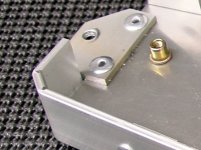
There are a few bends in the build (dashboard and skirt for electrical panel). These are not necessary and could be eliminated, however, with the Freud blade it is simple to do very nice ghetto bends without a metal brake by cutting halfway through the material along the bend line and then folding the stock by hand. This works perfectly for bends up to about 45 degrees at which point the edges of the kerf collide. For steeper (90 degree) bends, run a kerf down the bend line as above and then run an adjacent overlapping kerf a bit shallower to widen the overall kerf by about 75%. When you fold the plate, it will follow the deeper cut giving a nice straight bend, and the shallower cut to the side will allow a greater bend angle before the kerf edges meet. Slightly different treatment is necessary according to the ratio of plate thickness to kerf width. A sheet metal seamer is handy for bending the plate but is not necessary (Harbor Freight/Google ‘sheet metal seamer’).
22-02.JPG
Clearly this technique compromises the strength of the plate, but all bends in this project are cosmetic and the plate itself is far thicker than necessary so the 1/16” material left in the bend is still quite strong. In other situations, you can bridge the kerf with a fillet using HTS-2000 low temp brazing rod. I’m not a big fan of HTS-2000 for fabrication (vs. repair) but if you take the time to learn technique, it works pretty well.

Drilling

Not much to say – I used a drill press which made the work easier and more accurate. It was, however, not strictly required except for the counterboring – which could have been avoided with some other small changes to the build. In any case - clamp when drilling and use rubber pads on your clamps (or wooden blocks) to avoid marring the work (Google ‘clamp pads’).

Holes 3/8” and up are easily made using a stepped bit. Harbor Freight (‘step drill’) sells a couple of different bit sets that are similar to Unibits and will last a long time drilling aluminum. These bits do not grab and are easy to control. Lube freely while drilling.

Counterboring for pop rivet heads and rivet nut flanges is a bit problematic because the bottom of the counterbore should be flat which cannot be accomplished with ordinary twist drills -- and counter bores are a bit pricey. However, Dewalt sells a line of modestly priced bits with pilot drills ground into the tip (Google ‘Dewalt pilot point bit’); these have a virtually zero degree grind on the tip of main bit diameter. These are available at Home Depot or on-line and you can buy individual bits if you wish. I found it easiest to chuck up the bit in the press and turn the bit into the existing hole by hand for a few revolutions to slice a neat shoulder, but you should experiment for a technique appropriate for your equipment.

Simple Shaping

There is very little shaping in this project except for some simple outer radiuses. These were all done freehand on a disk sander with table that is part of a table belt sander. The disk was outfitted with 220 grit which cuts reasonably quickly and leaves a fair finish. Use the side of the disk that is turning downward into the table and smoothly rotate the work through the desired angle making multiple passes to sneak up on the final curve. Rough cut larger radiuses in the chop saw. Clearly this same work can be done by hand, but the powered disk cuts fast and gives a nice true perpendicular edge. Cool the work periodically in water and wipe dry – ripping apart metal molecules gets them very hot and bothered ;)

Finishing

Aluminum is easy to work by hand but quickly clogs any cutting tool. Make sure you have a wire brush with good straight stiff bristles to clear your files (stroke with the grain of the file) and do so frequently. Small holes (1/4” or smaller) are easily deburred with a conical deburring tool in a hand held hex driver handle (like a screwdriver) – Harbor Freight sells an inexpensive set (‘countersink deburring tool set’). Larger or elongated holes are quickly deburred with a swivel deburring tool (Google ‘swivel deburring tool’). Just sweep it around the hole and the bit will rotate and neatly chamfer the edge to a smooth bright bevel.

If you are careful and use padded clamps, etc, your work should come out of fabrication with the original finish. However, if it gets nicked or scratched, you can refinish it easily by wet sanding with 220 grit Wet n' Dry and a hard foam or rubber sanding block (auto supply stores) in long parallel strokes to simulate machine brushing (use a wooden guide for large surfaces). Use lots of water to avoid clogging the paper. Follow this with 400, then 600 grit using the same parallel strokes. Wash with Simple Green or dishwashing detergent. A higher polish is simple to achieve with something like Wenol polish, but simple sanding is adequate for a nice finish, remembering that aluminum is going to oxidize fairly quickly anyway. Anodized aluminum cannot be touched up once scratched – handle with care and dress the cut edges of unused stock to avoid scratching your supplies.

Fastening

Most of the fastening is done with aluminum Pop Rivets of different sizes – mostly 3/16” and 5/32”. I recommend name brand (Stanley) or bulk rivets sold through industrial suppliers – I’ve had very bad luck with Ace and other house brands that seem to have very poor quality control on the rivet diameter, requiring oversized holes. Pop rivet tools are available everywhere for as little as $4 and usually come with several nosepieces to handle different rivet diameters. Since the critical component that determines rivet tension is the breakable mandrel inside the rivet itself, almost any cheapie tool will give good results.

The bulk of the remaining fastening is removable and uses rivet nuts. There is a topic here on ES (Board index ‹ General ‹ Technical Reference Area ‹ Using Riv-Nuts) on setting these without a special tool but I bit the bullet and purchased a Marson RN-1 tool with some extra metric mandrels and nosepieces from Global Stores Group (http://www.blindrivetsupply.com). Once the RN-1 is adjusted for a particular rivet nut size, they can be installed in seconds, much like pop rivets. There are some other less expensive tools that set a single rivet size using a wrench and threaded nosepiece but those actually turn out to be less economical if you are interested in setting different sizes of rivet nuts. 5mm and 4mm rivet nuts are used in the build but the 4mm are not strictly necessary. Metric steel rivet nuts were obtained from JAY-CEE Sales & Rivet, Inc (http://www.rivetsinstock.com/) – these are zinc plated with sharp grabby ribbing and good quality threading.

So, that’s about it for the aluminum fab – nothing very exciting except the Freud blade which may be the best thing since zippers :).

(Next stop: aluminum battery boxes....)
 
AMAZING WORK !! :wink:

Pure quality , well organized, clean, Alot of talent here!

Congrat!

Doc
 
How comfort the Cloud 9 seat and Did you get it from Amazon online?
 
chroot said:
How comfort the Cloud 9 seat and Did you get it from Amazon online?
Yep - Amazon. I like it much better than the stock seat and I've ridden 45 miles without issue - pretty comfortable. But I think there may be some butt-training involved here - this summer after mine gets more bicycle-acclimated, I may look at some more classic non-gel designs.

Joseph C. said:
Best build and best build thread...ever! :D Very well done, teklektik.
Many thanks for the kind words ;)
 
Super clean build man. Very very nice. I'm jealous. Forget the 2wd haters, you've done a terrific job. Puts my Xtrcycle conversion to shame.
 
I am SOOO impressed with this build and the description!! I will go back many times to read and reread the different aspects of this build, and how to implement the different solutions for my own build.

Thanks very much for the thorough documentation!
 
Thanks guys - appreciated.

I always like the builds where I can take a little something away to use myself (or avoid!). Hoping folks get little mileage out of this one :)
 
OT - about ES Image Display

Hmmm - figured out the odd mix of true size and representational images in the earlier posts. It seems that if images are more than about 250K then a smaller representational image gets inserted in-line with a link to the original high-res version on image click; if less than 250K then they get displayed in-line at original size. And, not too surprisingly, the sliders show up on the images if the window width is too narrow...

Anyhow, I tweaked down the file sizes on a bunch of images in the initial posts so they would go in-line at original size. The increased compression makes them slightly less sharp than the originals, but it saves a lot of clicking...

Here's the same image but with different compression and file sizes - ES just handles them differently:

07_06_iv280.jpg
07_06_iv250.jpg
 
While installing the new front BB7 yesterday, I ran into a clearance issue with the BMC motor and argued unsuccessfully with the inside pad adjuster for a while. There is no way to get a torx driver into the adjuster and the manual adjuster wheel might as well be super glued in place...


So - a little project detour - I posted the fix here: DIY BB7 Brake Adjuster Tool.
 
Back
Top