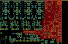
build your very own Lebowski controller !

Yes, the chip doesn't care whether 5V represents 100A or 300A, the chip just regulates until it sees a certain voltage swing coming from the current sensors...

IGBT's, for the voltages I run (80 to 120V) they don't make much sense so I've never used them. I would assume a IPM module has drivers etc inside, and will
just take the logic signals straight from the controller IC ? That's what I remember from the datasheets bluefang showed me.

I would use 2 version 1's and 2 version 2's. When running the HF tone, the chip is amazingly sensitive to the inductances it sees. Two HF tones on one motor
might bite each other. You can set the chips up to generate tones of different frequencies, I think this would give you a fighting chance. But what I would try is
a combination of a v2 and a v1 setup for push-start. In such a combination the v2 will give you torque from standstill. With this torque, at the slightest rotation
the v1 will start and then both controllers will be powering the motor. It would be interesting to see what happens. And, if it turns out two v2's works OK, I can
always reflash the v1's to v2's. The schematic change is really small as you can see from the KiCad database. (you can even run a v2 on a v1 board when you
connected the hall sensor from pin 6 to ground, this makes the FOC a little less accurate though)
 
IPM’s from what I have seen have the drivers on the module but still need a properly driven opto isolator and four isolated supplies from DC-DC converters. The components should only add about £20 to the cost.

Lebowski, how do the V1 and V2 controllers compare in usability and performance if lined up side by side?
As I’m just building my motor it shouldn’t be too hard to fit hall sensors but do I have to? And are there any advantages or disadvantages to either control method?
The back emf of my motor is probably going to be a bit lumpy due to my hallbach array having different sized magnets.
 
Ok, so current sensors are sorted just have to find an appropriate one for the job.

Standard IGBT needs a driver like the one you are using, IPM yes takes a logic signal but like IanFiTheDwarf mentions I would need to make a board with the opto and isolated DC-DC supplies on it for correct driving like the application circuit shown on page 6 of http://www.mitsubishielectric.com/s...ntelligentpmod/highspeedswl/pm450cla060_e.pdf tho atm we would be ignoring the fault output as your micro does not have an input for it.

A qty of 8 boards seems to makes sense for the PCB fab cost also then I could build 4 of each circuit design and bluefang could just swap boards as required and once he knows which combo would just need the chip flashed and not have to rework the boards.

Cheers

Chris
 
I'm building a igbt modual setup to run 411v and 400+ amps burst. Maybe you will want to use my igbt driver? What voltage and amperage do you want to run?
 
Hi Arlo1,

Bluefang is throwing out crazy numbers like 600V and 400A :p Which IGBT are you building a driver for? Certainly interested! what else can you tell me about it?

Cheers

Chris
 
1MBI8004UB-120. (800 AMP 1200 V FUGI IGBTs). What is bluefang using for a igbt? See my powerstage thread.
 
IanFiTheDwarf said:
IPM’s from what I have seen have the drivers on the module but still need a properly driven opto isolator and four isolated supplies from DC-DC converters. The components should only add about £20 to the cost.

Lebowski, how do the V1 and V2 controllers compare in usability and performance if lined up side by side?
As I’m just building my motor it shouldn’t be too hard to fit hall sensors but do I have to? And are there any advantages or disadvantages to either control method?
The back emf of my motor is probably going to be a bit lumpy due to my hallbach array having different sized magnets.

Just to compare v1 and v2:

v1:
- uses a 128 step sine table
- does not take battery voltage changing into account in the Field Oriented Control (so small, negligible errors are made)
- all variables and parameters in the setup menus have to be entered by the user
- during setup, measures motor parameters for the FOC but can be quite harsh and not so accurate when not set up properly.
- the reverse function works
- guaranteed to start and power of the line with the hall sensors, push start works very well with direct drive hub motors on bicycles

v2:
- uses a 256 step sine table
- measures the battery voltage and uses this in the Field Oriented Control for better accuracy (though I don't think there'll be any noticable difference with v1, it's more a nerd thing that I want it to bee 100% correct)
- only the basic info has to be entered by the user, many of the complex options in the setup menu can be autocompleted and calculated by the chip itself (but the user can still override)
- more accurate and gentle measurement and motor parameters, also measures and compensates for small differences in the current sensors (gain) and motor windings (impedance differences).
- settings can be saved and loaded from a hex text file
- reverse not implemented yet (will be added in the future)
- uses a high frequency tone (about 1.5 kHz) to measure the rotor position to provide torque from standstill. Tone switches off automatically after motor runs above a certain rpm, and back on when motor rpm drops.
- the HF tone is the only way to start the motor. In theory it should work with motors that have iron in the windings, which is basically all motors (except the AF motors I make myself which have air coils). If it fails though there's no push start or any other option to start the motor. This will be changed in future versions.
- CAN bus routines copied from v1, not tested for functionality though (have not heard anyone using this, so....).

The main FOC / sensorless algorithm is the same in both.

I don't think I'll develop v1 any further. For v2, first thing for me to add is the reverse, after that I want to add the possibility for push-start ( as I want this option for my current ebike ). I'm thinking about adding code for eliminating 'drag' from when the motor generates 5th harmonics (trapezoidal waveform motor, this motor in theory has a bit of drag when driven with a pure sine wave due to higher harmonics). I'm thinking about adding support for digital temperature sensors so that the controller will reduce phase current when the sensors register things are heating up. I also have some ideas for measuring the motor temperature from the increased phase winding resistance, but now we're really talking future versions :)
 
Ive followed this and some of the other Lebowski chip controller builds. I'm pretty up to speed. I'm definitely interested in a V2 board if anyone has extras in the US. Plenty of other projects at the moment.

Edit: found the answer to my question

Also am I correct in assuming that neither software will work with Induction motors? Cuz of the need for sensors and a tweaked control algorithm

Thanks
Kyle
 
I was just chatting to Bluefang about this, I'd interested in any Australia/Queensland group buy for boards+parts.

Cheers
 
v2 in action :D
this motor is very noise because, well, the motor plates act as cymbells... a hub would be much quieter

[youtube]JAbZChHpii8[/youtube]

P.S. Do not try this at home, 25s lipo in the livingroom is asking for trouble !!!
 
Hi,

Lebowski said:
this motor is very noise because, well, the motor plates act as cymbells... a hub would be much quieter
And because it's in an echo camber!!
 
parabellum said:
Is it working with you brain chip?
Sensor less start?
Is it the sound/tone for rotor positioning?
Shouldn't it work on iron cores only?
yes, it's the controller from this thread, with a v2 controller IC
Yep, sensorless start
The tone is indeed for detecting the rotor position
Apparently it also works on my triple stator motor :| the algorithm I use is very sensitive and can detect inductance differences of only a few %
 
Awesome project. Thanks for all your work Lebowski. I am currently in the planning stages of a small ev.

https://endless-sphere.com/forums/viewtopic.php?f=10&t=58417

Just a couple of quick questions.

Any idea of a ETA for reverse in version 2? The project is a small skid steer so I would need reverse.

Is there a really rough estimated BOM?

trevc2 if reverse is implemented in version 2 I would be keen to go in for an Australian order. I'm in NSW.
 
clow57 said:
Awesome project. Thanks for all your work Lebowski. I am currently in the planning stages of a small ev.

https://endless-sphere.com/forums/viewtopic.php?f=10&t=58417

Just a couple of quick questions.

Any idea of a ETA for reverse in version 2? The project is a small skid steer so I would need reverse.

Is there a really rough estimated BOM?

trevc2 if reverse is implemented in version 2 I would be keen to go in for an Australian order. I'm in NSW.

I've been thinking about reverse and will start with modelling / programming
end of next week. I would say it should definitively take less than 2 months (it's
a hobby so, I only work on it an hour here or there)...
BOM, just a coarse guess would be around $100 including PCB (paid $20 for mine,
shipping was $30 though :( ), plus $25 for the controller IC, plus the cost of the
output stage (lets say $30 per 6 FETs including caps)
 
Wow Lebowski you are a legend. Looks like I need to start gathering parts to make this thing and then I will hopefully get you to send me a brain after you are able to code in reverse.
 
Just curious with at least 2 drive motors and possibly several accessory motors I would probably need to run four controllers. Would there be a problem with running a separate power supply module that could feed all the boards. It would make assembly simpler. I am looking to make the entire controller box as modular as possible so I can upgrade/repair just certain pieces as the need arises. If I was to just buy ready made dcdc isolated converter or two one at 5v and one at 15v what sort of specs would I need for it? I have some other instruments and controls so having a power rail for everything seems like the way to go.

Thanks
 
It depends a little on the components (FETs) you use, but, guessing on the safe side, I would say every controller needs about 3W from the 15V and also about 3W from the 5V...
 
I am looking at doing a maybe a 12 fet with IRFB4110PBF's Do you see any problem with this?
 
Thanks again for the help. I am in over my head when it comes to pcb design. I have never used kicad before so a bit of a learning curve. I am currently trying to source parts (much more frustrating in Australia than in the States where I am originally from. The $30 min shipping means trying to source everything from one place.) I have found 4110s for $1.48 a piece which seems pretty good to me. :D

https://www.verical.com/part/566588-ACS758KCB-150U-PFF-T#searchTerm=248053&_i_=12&landingPage=catalogItemView&searchCriterion=mpnIDs&searchName=

I have a couple more questions.

Would the cap arrangement and size you used for the 4115s also work for 4110s? If not what would I need?

In terms of bus bar is thinner and taller better, or would I be better with thicker bar stock?

If I am using an off board power supply can I leave the area in red in the photo completely unpopulated or are there still some necessary components?
Where would I make the 5v and 15v connections?


Thanks
 

Attachments

  • controller11 copy.jpg
    controller11 copy.jpg
    123.6 KB · Views: 3,290
Back
Top