build your very own Lebowski controller !

Lebowski said:
The dream chip would have a few 100k fpga cells, an ARM core and 4 high quality ADC's... all in a 40 pin DIL for only $ 1 :mrgreen:

If you plot the curve we've seen in uController development, it would seem your wish will be realized
In a relatively short period of time.
 
Hey All;

Has anyone in the US ordered a batch (and have extras) of the PCBs for this controller? I'd like to get at least two boards and build up a couple controllers.

BTW: I want to be able to go high voltage - 150V or so. I'm looking at a future 24S LiPo (98.4) volt ebike.
 
Catching up on ES threads, nice job Lebowski.

Would it make sense to use some common mode ferrites on the gate twisted pairs to avoid unfortunate series resonances there that might shunt significant currents onto the control pcb? Everyone is going to make lead lengths and routing different, so these resonances are somewhat uncontrolled. The ferrites can be chosen to be lossy more than inductive, so provide relatively broadband common mode isolation.
 
To be honest, i don't know. I don't have them... i always feel that ferrite beeds are used to fix bad engineering, except for in hf circuits. You, know, they are the duct tape of electronics.
 
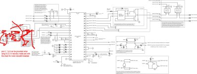
Lebowski, I think you got an error in the schematic in your Kicad files. The 2200ohm resistors used to get 2.5V midpoint for BEMF measurement in the image schematic for v2.xx here:
http://endless-sphere.com/forums/viewtopic.php?f=30&t=36602
have the value 22k in the Kicad schematic, but from what I can tell from your pictures, the actual value you used was indeed 2k2. Also in the Kicad schematic you use a 2.5V resistor voltage divider for each phase, this is not illustrated in the image schematic in the above thread. Here is only 1 resistor divider for 2.5V midpoint used for all 3 phases.
Also, I cannot see the connection from the resistor divider and protection diodes, to the controller IC in the Kicad schematic. The R_mot resistors, are they what you call Rb or Ra in the image schematic?

I'm sorry, but Kicad is new to me so I might be asking dummy questions.
 
Futterama said:
Lebowski, I think you got an error in the schematic in your Kicad files. The 2200ohm resistors used to get 2.5V midpoint for BEMF measurement in the image schematic for v2.xx here:
http://endless-sphere.com/forums/viewtopic.php?f=30&t=36602
have the value 22k in the Kicad schematic, but from what I can tell from your pictures, the actual value you used was indeed 2k2. Also in the Kicad schematic you use a 2.5V resistor voltage divider for each phase, this is not illustrated in the image schematic in the above thread. Here is only 1 resistor divider for 2.5V midpoint used for all 3 phases.
Also, I cannot see the connection from the resistor divider and protection diodes, to the controller IC in the Kicad schematic. The R_mot resistors, are they what you call Rb or Ra in the image schematic?

I'm sorry, but Kicad is new to me so I might be asking dummy questions.

I had a quick look at the pictures (I don't have Kicad here at work), but the most usefull one is dsc01466 on the first page.

The schematic in the Kicad is a little bit different from the jpg schematic picture in the other thread. I decided to get rid of the 2k2 divider and use a dedicated one for each phase.
The dedicated one as in the Kicad should be 22kOhm for the divider, and then the resistance from the motor (R_mot) in my build is 11kOhm.

When my last company went bust me and a friend divided all the components among ourselves, so I got about a million resistors all in funny values (from the E24 series I believe).
All of these have 4 instead of 3 color bands for the value.
If you look at dsc01466, you can see on the bottom the 11kOhm R_mot resistors (brown - brown - black - red). Above that are the voltage devider resistors of 22kOhm (red - red - black - red)


So, the Kicad is correct.
 
Ah, so the whole resistor divider arrangement is changed between the jpg schematic and the Kicad schematic. The 10k "Ra" from the jpg is all gone and the way it is all connected is different. Ok, now it makes sense. Also when printing the Kicad shcematic, I get some labels e.g. "phase_A_fb" that is not shown inside Kicad, so now I can see what part of the resistor divider is connected to the controller chip.
 
Lebowski, since the 1N4148 diodes are there to protect the PIC, how can the PIC stay protected when the forward voltage of the diodes are some 0.6V but the absolute maximum voltage on any PIC input pin must not exceed VDD + 0.3V? The 0.6V forward voltage of the 1N4148 would allow for a max voltage on the PIC pin to be 5.6V, right? The reason why your controller is working, could it be that the PIC's own internal voltage clamps are conducting all the current (around 4.5mA at 150V with 33k resistor between phase and PIC input)?
The PIC's internal protection diodes are good for 20mA so the PIC would survive, but the 1N4148 are doing nothing in the circuit.
 
Futterama said:
Lebowski, since the 1N4148 diodes are there to protect the PIC, how can the PIC stay protected when the forward voltage of the diodes are some 0.6V but the absolute maximum voltage on any PIC input pin must not exceed VDD + 0.3V? The 0.6V forward voltage of the 1N4148 would allow for a max voltage on the PIC pin to be 5.6V, right? The reason why your controller is working, could it be that the PIC's own internal voltage clamps are conducting all the current (around 4.5mA at 150V with 33k resistor between phase and PIC input)?
The PIC's internal protection diodes are good for 20mA so the PIC would survive, but the 1N4148 are doing nothing in the circuit.

You're right, the protection diodes in the chip take most of the current. But I wouldn't feel confident taking the 1N4148's out though...
 
Well, I don't remember exactly... back in the days of v1.01 once it happened that I was down in the village and the bike wouldn't start anymore. When I hooked
it up to the computer I found the EEPROM memory holding all the settings was wiped clean. I then decided to write the settings to the program memory instead of
the EEPROM memory. Since then I've had no problems anymore. But somewhere during this process I upped the voltage to 5.1 and found it worked better, I just
don't remember whether this was during the EEPROM programming or later when I changed to program memory programming...
 
Lebowski said:
Futterama said:
Lebowski, since the 1N4148 diodes are there to protect the PIC, how can the PIC stay protected when the forward voltage of the diodes are some 0.6V but the absolute maximum voltage on any PIC input pin must not exceed VDD + 0.3V? The 0.6V forward voltage of the 1N4148 would allow for a max voltage on the PIC pin to be 5.6V, right? The reason why your controller is working, could it be that the PIC's own internal voltage clamps are conducting all the current (around 4.5mA at 150V with 33k resistor between phase and PIC input)?
The PIC's internal protection diodes are good for 20mA so the PIC would survive, but the 1N4148 are doing nothing in the circuit.

You're right, the protection diodes in the chip take most of the current. But I wouldn't feel confident taking the 1N4148's out though...
What about using 2.5V zeners from the midpoint voltage of 2.5V to the analog input? Then the zeners would conduct as soon as the voltage got above 5V or below 0V, saving the PIC internal diodes from all the work AND keeping the analog input voltage within the specs of the PIC.

Wait a minute, if current is flowing through the zener and then through one of the midpoint resistors, the midpoint voltage would change, so the above solution with zeners would probably not work.
 
Lebowski said:
plus I'm always a bit afraid zeners will be too slow...
Yeah, I was thinking the same thing, but still they would probably take a lot of load off the internal diodes in the PIC.

Well, I have decided to try without the 1N4148 diodes. I will do a test first where the 1N4148 are in place, and then measure to see if they actually conduct any current at all, if not, I'll go ahead and take them out, and we'll see if my PIC will hold up, I'm sure it will since the current is well below the max current for the internal diodes.
Cost is not my reason for wanting them removed, space is only a minor reason but if they really don't do anything, it would be nice to know they can be left out without damaging the PIC.
 
Futterama said:
Lebowski said:
plus I'm always a bit afraid zeners will be too slow...
Yeah, I was thinking the same thing, but still they would probably take a lot of load off the internal diodes in the PIC.

Well, I have decided to try without the 1N4148 diodes. I will do a test first where the 1N4148 are in place, and then measure to see if they actually conduct any current at all, if not, I'll go ahead and take them out, and we'll see if my PIC will hold up, I'm sure it will since the current is well below the max current for the internal diodes.
Cost is not my reason for wanting them removed, space is only a minor reason but if they really don't do anything, it would be nice to know they can be left out without damaging the PIC.

With the new v2.21 I added recovery to the chip. When running in this mode the entire path between the motor phase voltages
and the chips ADCs CAN be omitted, IF ALSO THE CHECK FOR MOTOR STANDSTILL AT STARTUP IS DISABLED.
 
Lebowski said:
With the new v2.21 I added recovery to the chip. When running in this mode the entire path between the motor phase voltages
and the chips ADCs CAN be omitted, IF ALSO THE CHECK FOR MOTOR STANDSTILL AT STARTUP IS DISABLED.
I think that requires a bit more explanation. The 2.5V resistor divider is only there to check for a slow running motor? So without the check for standstill, basically only a current limiting resistor is needed between the phase wire and the PIC pin?
What consequences would it have for the controller to disable the check for standstill?
 
Oh! That would free up some pins then :D

I thought they were used for zero crossing detection, but I guess you use the phase current measurement for than instead.

What consequences would it have for the controller operation in general to disable the check for standstill?
 
Futterama said:
Oh! That would free up some pins then :D

I thought they were used for zero crossing detection, but I guess you use the phase current measurement for than instead.

What consequences would it have for the controller operation in general to disable the check for standstill?

Well, it's a safety check. Before I had recovery the voltage sensing was the only way the controller could tell the motor was standing
still, and the motor had to be standing still for the controller to be able to grab control. As it is sinewave FOC, all three motor
terminals are powered all of the time, so if the controller would grab control without being in sync with the motor, all hell would
break lose (the motor will freeze and quite possibly make you crash, and blow up the powerstage too).

Now the new recovery mode can come in sync with an already running motor and it doesn't need the voltage info for that. There is
a bit of danger here though in a sense that looking at the motor voltages and waiting for those to be 0 (or 2.5V actually with the
schematic I used) will also tell you whether a FET is conducting when it shouldn't. With a blown (always ON) FET the controller would
be stuck in drive_0, so a safety measure. When disabling the motor standstill check also the (implied) FET check is disabled.

The recovery is programmed such that whenever something goes wrong like an error current violation it will always go to recovery mode
(instead of drive_0 as before). In recovery it will try to sync with a running motor for a preset amount of time (a setup menu option), if
it doesn't sync it will jump back to drive_0. There then a blown FET would be detected, if the check for motor standstill is enabled.
If checks are disabled (there's also a throttle closed check in drive_0) it will go back and try to recover again, indefinatly.
 
Ah, so if a FET is blown and always ON, the voltage would never be 2.5V for all 3 phases, and the controller won't "restart".

If a FET was shorted out with motor standstill disabled, and we have desat detection in the output stage, then this would detect the fault too, right?
 
Futterama said:
Ah, so if a FET is blown and always ON, the voltage would never be 2.5V for all 3 phases, and the controller won't "restart".

If a FET was shorted out with motor standstill disabled, and we have desat detection in the output stage, then this would detect the fault too, right?

I would say so, yes.
 
Back
Top