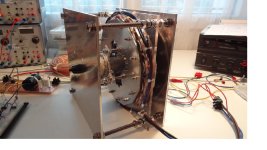
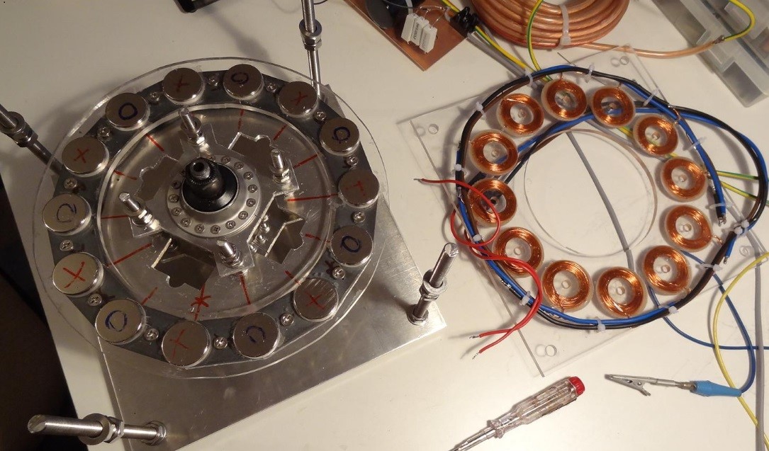
Building a triple stator axial flux motor

Hi,
This thread is making it possible for me to try a motor build - big thanks!
I am thinking of copying straight off but use a single speed hub, gives me 80 mm of motor width to play with instead of around 50.

I have only a basic understanding of the mechanisms involved so i have a few questions:
If scaling to get max number of plates i might get 4 or 5 stators in 80mm width. Volts needed are proportional to stators so then need to run 80*(4/3) V controller for four stators, correct?
Building a controller is outside of my limits, what kind of controller is good with a 4 stator setup of this motor?

I have a CNC milling machine that i built as a diy project so i can mill any plates or holes needed.
If using other shape of coils and magnets then what would be your recommendation?

I am also considering increasing diameter to get added torque but then i think the pole/coil setup need to be changed and that would create an additional 1000+ questions.

Lebowski: If you have thought of a optimized design that you don't have the energy at this time to do i'll be happy to do the building in your place :D
 
Amazing build...any updates?

I see the two inner rotors have a 1.0mm iron plate in the middle.
I understand the outer rotors have the thicker iron backplate, so that there is basically no magnetic attraction of a paperclip on the outside of the iron.
...but how/why did you work out the inner rotor iron plate to be only 1.0mm thick??
Another dummy question, because this stuff is too interesting....the two opposite magnets on the inner rotor obviously attract, or they wouldn't stay in place right?? so the windings in the same position on the two stators have the current running in opposite directions??
 
well the inner iron plate is actually not necessary, it is purely there for mechanical reasons. If you would know how to solidly glue the magnets into the acrylic
plate then you could make the middle rotor plates like that. But since the attraction forces between the magnets are so big I decided for the 1 mm plate. It prevents
the magnets of the middle plates from tearing loose from the acrylic and flying to the left or right. There are no saturation specs for the 1mm plate as there is no
lateral field.

The magnets in the inner rotor attract. So for one magnet stack (going from one endplate through the two middle plates to the other endplate) the field
is in the same direction. So the currents in the stator windings are all in the same direction.
 
I run this motor with a sinewave controller and it behaves flawlessly. The motor has quite some inductane, if i remember correctly abour 20uH per coil and each phase has 9 coils in series. V1 has 75uH per coil with 3 in series.

To get an idea of the inductance, google 'online inductance calculator', choose the right topology and enter your numbers
 
I have some really dumb questions.
I have a totally different application but like the basic layout very much.
I know you would loose power, btutcould you have one plate of magnets, or do you need two plates for it to work?
I am going to go and read the references pointed out earlier, but what it the advantage of 3 stator plates?
- if it is ease of?
- is it to have 3 coils on seperate cycles in the same vertical axis?

If I do not need as much power, could I get by with one or two?

Sorry for the dumb questions.
 
Yes, this design (axial flux) can work well with only one stator and one magnet rotor.

Why add more stators and rotors? Once the biggest diameter of the motor is determined for the application, you can make the motor more powerful by adding more stators and magnet rotors, which of course will make the motor wider.
 
spinningmagnets said:
Yes, this design (axial flux) can work well with only one stator and one magnet rotor.

Why add more stators and rotors? Once the biggest diameter of the motor is determined for the application, you can make the motor more powerful by adding more stators and magnet rotors, which of course will make the motor wider.

Thanks for the quick reply.
I do not want to divert this very good thread, so I will post my questions about my specific design in a new thread.

BUt I think that this design has a lot of promise for what I am thinking about. I have a lot more reading to do.
 
I think that this design has a lot of promise

If there is a trade war with China, and a shut-down of available hubmotors/common mid drives...this motor can be made from raw stock that can be sourced from a variety of suppliers...

Every design change option in electric motors has a benefit/drawback that has to be weighed out, but...if the main criteria is DIY?....THIS motor is the one to make in your garage.
 
hi friends! need some help!
i want to build same Axel Flux PM generator BUT.....

But i dont know how to connect same phases from different stators ? Help!
For example... we have 3 stators with 3 phases (A, B, C) in each!

For 1st stator we have phases A1,B1,C1:
A1-start A1-end
B1-start B1-end
C1-start C1-end

For 2nd stator we have phases A2,B2,C2:
A2-start A2-end
B2-start B2-end
C2-start C2-end

For 3rd stator we have phases A3,B3,C3:
A3-start A3-end
B3-start B3-end
C3-start C3-end

--------------------------------------------------
HOW TO CONNECT Same PHASES From different stators BETWEEN EACH OTHER?
maybe like this...
----------------------------------------
----------------------------------------
Phase A
A1-start - TO OUTPUT; A1-End + A2-Start; A2-End + A3-Start; A3-End - TO OUTPUT
Phase B
B1-start - TO OUTPUT; B1-End + B2-Start; B2-End + B3-Start; B3-End - TO OUTPUT
Phase C
C1-start - TO OUTPUT; C1-End + C2-Start; C2-End + C3-Start; C3-End - TO OUTPUT
---------------------------------------

Am i right? do you can help?
 
-----------------
Are they mechanically synchronized/bound?
Is it AC or rectified to DC (pulse style)?
-----------

- Are they mechanically synchronized/bound?
- Is it AC or rectified to DC (pulse style)?

- I dont know) This is just done generator... I simple have 4 rotors and 3 stators betveen with slots. That's all... In rotors i have 10 poles in each, in stators i have 9 slots in each. I want to have all stators with "STAR" winding. From each stators i have 6 outputs cabels (A-phase-start,A-phase-end; B-phase-start,B-phase-end; C-phase-start,C-phase-end). thats all what i have)
I want connect same phases from 3 stators betveen each other.... help) PLS!
 
for winding i used this site-calculator http://www.bavaria-direct.co.za/scheme/calculator/
with parameters - Slots 9; Poles 10.
All stators done like in calculator picture.. all stators have same diameter, width, heigh, alss stators are same...
 
1)If you need 3phase AC output you could connect in Star and parallel stators, but they must be perfectly aligned and rotors poles to. (negative: you could have some recirculating currents and uneven load sharing)
2)If you want quick DC output and no brainer you could connect in star and rectify output of every stator individually, then parallel. (negative: loses on rectifiers sum up)

If they are aligned, you could do a lot of funny things, like series star connection of all stators or pairs of stators, all depends on V you need at the end. If they are shifted, to reduce cogging or whatever other reason, you are practically bound to work on every stator individually and then parallel rectified outputs, there is also no warranty to even distribution of load at the end.

My preferred, less lossy and best distributed config would be with equally wound and aligned stators and aligned rotors, then you star connect 1st stator and series connect all others, in chain. Like 1st stator inns ABC connected/1st stator A out to 2nd stator A in/2nd stator A out to 3rd stator A in ... and so on. You will have 3 phases on the output, highest V configuration possible and even current distribution on all stators.
Hope it helps.
 
Lebowski this is along similar lines as your motor so i thought you would be interested. Here is a design i might try using a spare geared hub magnet rotor i have lying around gathering dust to build something similar to the motor discussed in this rather thin article from UQ (University of Queensland Australia
https://www.researchgate.net/publication/238048186_Design_optimisation_of_Ironless_Motors_based_on_Magnet_selection

They also use some interesting methods for determining the optimal pole numbers and rotor geometry. The design is related to yours in that it uses no iron core in the stator but is a radial flux machine.

I have the idea to adapt this design to a 16 pole rotor from a bafang bpm geared hub using a coreless 48 pole overlapped integer winding scheme. Integer winding patterns are usually avoided in hub motors because of very strong cogging causing difficult startup drag. I like ironless designs because tehy are inherently lacking in the major motor loss of iron eddy currents. The main attraction of ironmless construction is low rolling resistance in direct drive bicycle systems and high efficiency for power and regen

the problem i face is choice of turn count and litz bundle thickness to make a motor with a suitable KV for the application which would be 2.5 kw max and 48volts nominal i would drive this with a vesc field oriented controller that has very good programability and is able to cope with much lower inductance windings than most ebike cntrollers and is the only controller i know of that is most similar to yours and may be in some aspects be a ripoff or parallel evolution to your FOC controller yours was available before the vesc was around as far as i know and the vesc uses many similar strategies to drive motors and detect their parameters. the math is new to me but probably not beyond my ability so i have some questions, how does one calculate the required wire bundle size and turn count to get a desirable KV , lower than 50 would be good for the application and how about flux density and how this will affect the needed turn count and bundle thickness.

interestingly the UQ design uses a rotor with a return path iron ring placed on the other side of the stator windings from the magnets for providing a stronger return path for the outer ring of magnets through the coils, I wonder why you did not use a similar backing iron to reduce magnet requirements ?
 
i'm in a process of building coreless axial flux motor like this one .
can anybody tell me what is the rule of thumb for coil vs magnet size ratio ?
in this case i see the coil is bigger then the magnet .

lets say i'm not limited by number of turns in the coil , using disc magnets with 30mm diameter , what will be the optimal inner and outer coil diameter ? and also is there optimal coil thickness ?

are there any designs where the coil and magnet have different shapes ?
thanks guys
 
Found some time to write about this. I'm glad its finally out there. I hope this raises some interest.

 
Last edited:
Back
Top