Dual rotor axial flux motor design

Okay, some updated results. The model I'm currently using has 2 mm thick N30SH magnets, 1 mm airgaps, and 18 turns on each core (2x9 turns). This works out to give a Kv of about 140 RPM/V. With 16 turns (2x8), it was around 160 RPM/V. This configuration gives a peak flux density of about 1.75-1.8 T in the cores. It would definitely be possible to achieve the same Kv of around 150 using fewer turns by increasing the flux, the only question is if saturation will come into play and limit the torque too much. For now this seems like a good working configuration.

I've decided that I need to take a step back and look more closely at how I'm calculating the torques. I'm still using the two different techniques and so far no matter what I've tried they don't agree with each other (right now, off by more than a factor of two), and neither agrees with the torque I expect from the Kt (one higher, one lower). That doesn't give me a warm fuzzy feeling. I'm going to take a little bit of time and try to find some good reference cases, where I can either calculate the forces myself by hand or have some experimental results to compare against.

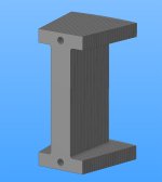
I can also change the model to allow for 1 mm diameter holes in the cores, as shown below. I don't think it will affect things very much.
 
Thanks Eric.

For 160Kv (16t) the strip would be 0.35mm thick which gives a phase resistance of 0.25 milliohms. So, phase to phase resistance for wye is 50 milliohms.

Comparing with the outrunner above [ http://www.scorpionsystem.com/catalog/motors/s55/S-5545-150KV/ ], which has an Rm of 30 milliohms (for 150Kv), this topology doesn't seem to give an easy advantage....
 
Is there any place to get started with FEMM? Or a quick start guide? Maybe a Femm work group? I just want to get started with it. I have never used it before.
 
I think the next move should be to try increasing the proportion of iron. At the moment we have 1:2 iron to copper. Maybe increase the core width from 3.2mm wide to 4.2mm (keeping the heads the same)? Stick with 2mm thick magnets, up the strength to N48 and reduce the airgap slightly, to get the same flux density as before?
 

Attachments

  • 4.2mm-wide-core-module.jpg
    4.2mm-wide-core-module.jpg
    38.6 KB · Views: 1,717
Scorpion S-5545 10t Delta: http://www.scorpionsystem.com/catalog/motors/s55/S-5545-150KV/

Weight 1.026 Kg

Kv 150 rpm/V

Kt 0.0637 Nm/A

Rm 0.03 ohms

Km is 0.0637 / SqRt 0.03 = 0.37

[ 0.37 / 1.026 = 0.36 ]


Astro 3210 8t Wye: http://www.astroflight.com/pdfs/3210WEB.pdf

Weight 1.0 kg

Kv 169 rpm/V

Kt 0.0565 Nm/A

Rm 0.08 ohms

Km is 0.0565 / SqRt 0.08 = 0.20


Ok, the Scorpion is in the lead.... :)
 
http://www.ijme.us/cd_08/PDF/190%20ENT%20202.pdf has some discussion on rectangular vs trapezoidal coils. This applies as well to the coil ends even if the actual coil lam is rectangular only. Sine type Bemf and minimized torque ripple, see Figures 10-14.
kenkad
 
Miles said:

Specific Km seems like a good value for comparison. It doesn't say everything though, because it doesn't say how much iron losses the motor has. If you use powerful magnets, and/or if you substitute iron for copper, Km will increase (up to a point). But both of those changes could also increase the iron losses, which could make the nominal power decrease despite better Km. And if the motor has good thermal design, it could in practice get higher specific torque despite having a lower Km number.

It would be interesting to see what the ratio between parasitic and copper losses are in different motors at nominal speeds and loads.

How much heat do you expect your motor be able to dissipate?

EDIT:
Putting the C80100-180 here for comparison.

Weight = 1.81kg

Kv = 180 RPM/V

Kt = 60 / (2*pi*180) = 0,053 Nm / A

R = 0,017

Km = 0,053 / SQRT(0,017) = 0,407

Specific Km = 0,407 / 1.81 = about 0,22
 
bearing said:
Specific Km seems like a good value for comparison. It doesn't say everything though, because it doesn't say how much iron losses the motor has.
True. It's a good comparison for my goal of highest specific continuous torque, though. Capturing everything in a single "figure of merit" is quite tricky :) How could we modify specific Km to give at least a kind of "weighting" for iron losses? It's unusual for specifications to even bother giving the voltage at which the no load current measurement is taken, let alone giving 3 values to work out how it varies....

It might be good to have a thread to discuss motor comparison in...

Thanks for the C80100-180 data! :)
 
bearing said:
How much heat do you expect your motor be able to dissipate?
In this respect, it should have a significant advantage over most outrunner designs. I've never done any heat calculations before - have to find out about that....
 
kenkad said:
http://www.ijme.us/cd_08/PDF/190%20ENT%20202.pdf has some discussion on rectangular vs trapezoidal coils. This applies as well to the coil ends even if the actual coil lam is rectangular only. Sine type Bemf and minimized torque ripple, see Figures 10-14.
kenkad
Thanks Ken! I'll have a read. Different trade offs with coreless though, I guess...
 
Miles,
Of course, coreless is a different situation. I had seen that paper before and had to relocate it. It says to me that trapezoidal flux director ends on the stator coils and rectangular (or square in your case) magnets on the rotors is the way to go because it is very difficult and expensive to get wedge shaped magnets (Shane found that out). The other number that I have seen in a paper is that the magnetic fill must be over 75%. What does your magnetic fill calculoate out to be? My two magnetic rings per rotor are both 78% fill. Sine Bemf and sine drive is critical to quiet motor operation. Shane Colton confirmed that over two years ago in his research work and subsequently in his thesis. Wish I could get him to do more motor design work now. His interest has gone elsewhere. As you know, I am more interested in a multi 3-phase design rather than a single 3-phase layout. But, I am curious about how yours turns out first. May save me some heartache. Our dimensions are curiously very very similar.
kenkad
 
Ken,

I went for uniform central core to avoid different lamination sizes. Having done that, there was less incentive to use wedge shaped magnets, anyway - it would mean that the outer radii of the core would saturate before the inner..... Also, the square magnets help create a more sine like BEMF, in my case.
 
Miles said:
bearing said:
Specific Km seems like a good value for comparison. It doesn't say everything though, because it doesn't say how much iron losses the motor has.
True. It's a good comparison for my goal of highest specific continuous torque, though. Capturing everything in a single "figure of merit" is quite tricky :) How could we modify specific Km to give at least a kind of "weighting" for iron losses? It's unusual for specifications to even bother giving the voltage at which the no load current measurement is taken, let alone giving 3 values to work out how it varies....
How about multiplying whatever no load amps value is available by Kt, dividing by mass and keeping it as a separate figure for "specific parasitic torque"?
 
Useful introduction to power losses in wound components:
http://info.ee.surrey.ac.uk/Workshop/advice/coils/power_loss.html
Written WRT transformers but also relevant to motors
 
Miles said:
How about multiplying whatever no load amps value is available by Kt, dividing by mass and keeping it as a separate figure for "specific parasitic torque"?
Scorpion S-5545:........0.0813 Nm/Kg [1.31A @ 10V]
Astro 3210:..............0.0395 Nm/kg [0.7A]
Turnigy C80100:.........0.1025 Nm/kg [3.5A]
 
Miles said:
Miles said:
How about multiplying whatever no load amps value is available by Kt, dividing by mass and keeping it as a separate figure for "specific parasitic torque"?
Scorpion S-5545:........0.0813 Nm/Kg [1.31A @ 10V]
Astro 3210:..............0.0395 Nm/kg [0.7A]
Turnigy C80100:.........0.1025 Nm/kg [3.5A]

Good suggestion!
Since it's no load torque, I suggest calling it Specific Tnl.

Code:
Motor               Specific Km     Specific Tnl
Scorpion S-5545     0.36 Nm/√(W)    0.081 Nm/kg
Astro  3210         0.20 Nm/√(W)    0.040 Nm/kg
Turnigy C80100      0.22 Nm/√(W)    0.10  Nm/kg
Thingap TG2311      0.14 Nm/√(W)    0.13  Nm/kg

I found a that Thingap have good specs on their motors. Added TG2311 for comparison. It's a 0,6kg ironless core radial flux PMSM.
http://www.thingap.com/pdf/2011/tg2311ss.pdf
 
bearing said:
Miles said:
Miles said:
How about multiplying whatever no load amps value is available by Kt, dividing by mass and keeping it as a separate figure for "specific parasitic torque"?
Scorpion S-5545:........0.0813 Nm/Kg [1.31A @ 10V]
Astro 3210:..............0.0395 Nm/kg [0.7A]
Turnigy C80100:.........0.1025 Nm/kg [3.5A]

Good suggestion!
Since it's no load torque, I suggest calling it Specific Tnl.

Code:
Motor               Specific Km     Specific Tnl
Scorpion S-5545     0.36 Nm/√(W)    0.081 Nm/kg
Astro  3210         0.20 Nm/√(W)    0.040 Nm/kg
Turnigy C80100      0.22 Nm/√(W)    0.10  Nm/kg
Thingap TG2311      0.14 Nm/√(W)    0.077 Nm/kg

I found a that Thingap have good specs on their motors. Added TG2311 for comparison. It's a 0,6kg ironless core radial flux PMSM.
http://www.thingap.com/pdf/2011/tg2311ss.pdf
Ok, "Specific Tnl" :)

Did you forget to divide Tnl by 0.595 kg? I make Specific Tnl 0.1290 Nm/kg Certainly makes it look even less impressive :shock: Where are all the losses coming from? Eddy currents in the copper?
 
Miles said:
How about multiplying whatever no load amps value is available by Kt, dividing by mass and keeping it as a separate figure for "specific parasitic torque"?

This is a good start, but this is a little bit of a slippery quantity since the RPM will factor significantly into those losses.

Option: Take this quantity and multiply by no-load speed (convert units to rad/s first); the resulting units will be loss per mass in W/kg. This is the same way that losses for electrical steel are expressed. May penalize high-RPM motors? Not sure.

In other news, my FEMM simulations are going less than well. Getting useful numbers for torque is proving difficult as I can't get the different methods to agree on a single number. I just started a new run of simulations to try out a different approach. Should have some results late this afternoon.
 
rhitee05 said:
Miles said:
How about multiplying whatever no load amps value is available by Kt, dividing by mass and keeping it as a separate figure for "specific parasitic torque"?

This is a good start, but this is a little bit of a slippery quantity since the RPM will factor significantly into those losses.

Option: Take this quantity and multiply by no-load speed (convert units to rad/s first); the resulting units will be loss per mass in W/kg. This is the same way that losses for electrical steel are expressed. May penalize high-RPM motors? Not sure.

A lot of the time we're already starting with a slippery quantity, though.... Most specifications don't even give a voltage to go with the Io figure :(

Good suggestion, though.
 
This is a good read:

Design, Comparison and Experimental Evaluation of
Non-OverlapWinding Radial Flux Permanent Magnet Hub
Drives for Electric Vehicles
 

Attachments

  • rix_design_2011.pdf
    5.7 MB · Views: 123
Those thin gap motors are damb cool!!!
 
Back
Top