"E-Zilla" w/ Cro Motor mid-drive * UP-DATE Chopping Frame!!*

Wow!

Nova Cycles rocks!

I got the disc tabs in two days! :D

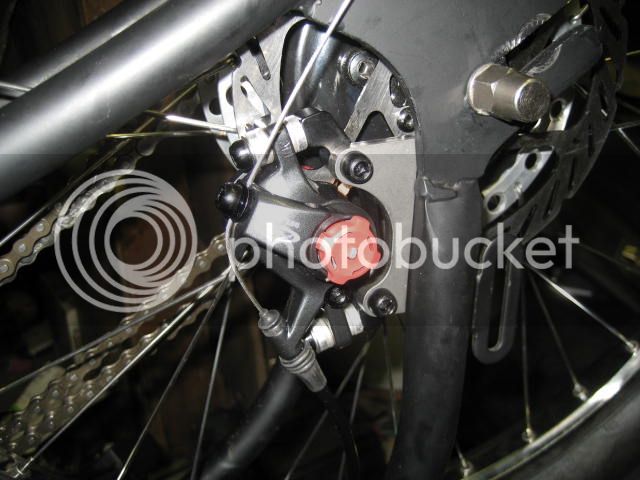
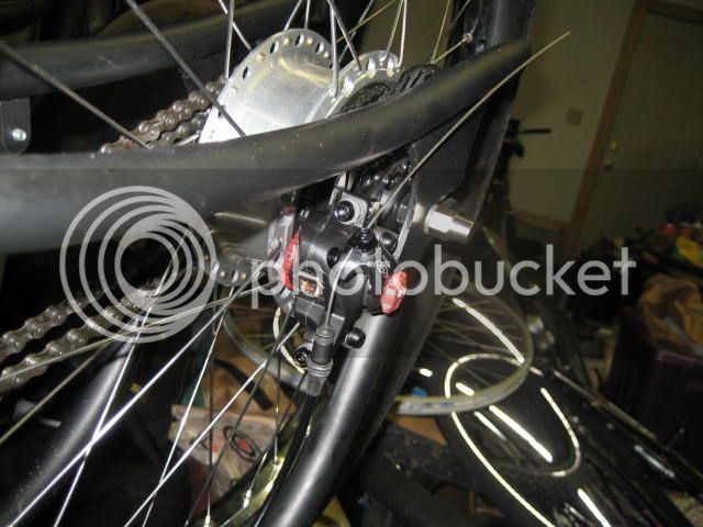
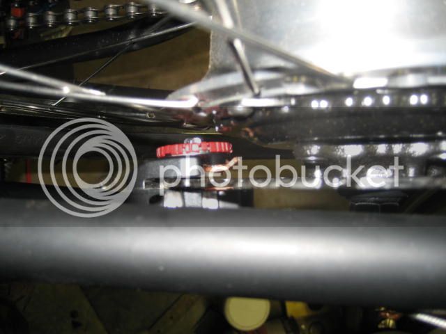
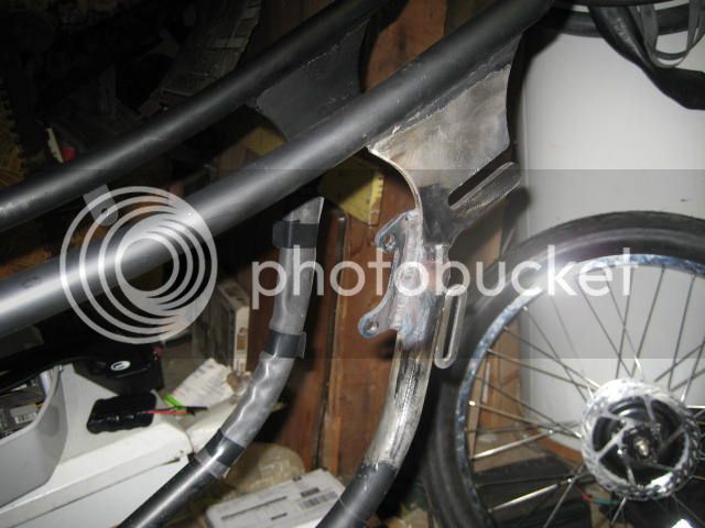
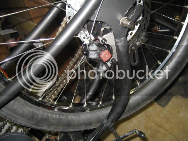
Here are some pics, looks like it's going to be a lot easier than I thought mounting the tab:

NewCruiserRearDiscMount003_zps36d790d3.jpg


NewCruiserRearDiscMount004_zps2181d1a4.jpg


NewCruiserRearDiscMount005_zps17cf859c.jpg


NewCruiserRearDiscMount006_zps3728f7a7.jpg
 
Finally got things welded! :D

My neighbor did this for me as a "Christmas Gift!" so I am very VERY happy to have it done!

Was a bit of a chore taking off the powder coat back the recommended 3-4 inches from where we welded, but I am very glad I bought 2 styles of disc brake tab, because the slimmer one turned out to be the best, and we just used a cardboard template between the two pieces to make the bit of 3/16" plate into a suitable filler at just the right size, and fit it up just like we wanted it!

CruiserBrakeTabWelded001_zpscd974853.jpg


I'll get some more pics of it together so the proper fit can be appreciated, but it's cold in the garage, so I'm happy to be finished for today! :wink:
 
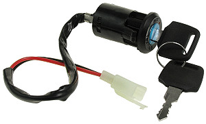
Got some more progress, after getting a really cheesy ignition switch from Ebay (looked fine in the pictures .. :roll: :p ) I found one that I really like! It locks the key into position when it is "on" and could be attached to a clip much like you would with a motorcycle or sports car so you're not hanging an entire key-ring on the switch.

The really nice thing is it's just about 1 inch in diameter, so if you have an 1 & 1/8 size steer tube, you could remove the cap and star nut on top and put one of these switches in a nice natural spot!

I have a 1 inch steer tube, so it won't work on this bike and I like having it closer to the controller anyway.

Here is the site I bought it from: http://www.electricscooterparts.com/keyswitches.html

SWT-230.jpg


They have phone support too, was really nice to get someone on the phone to measure the body of it before I ordered it!

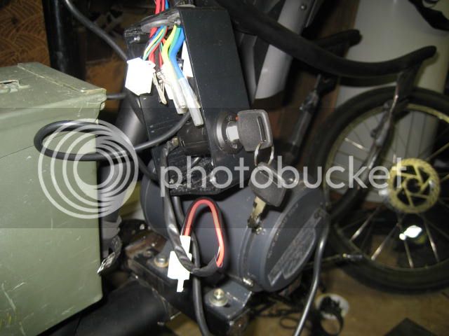
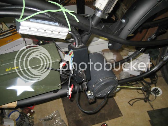
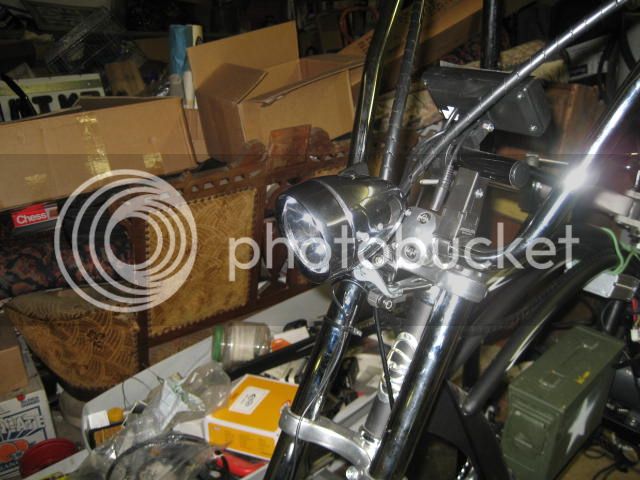
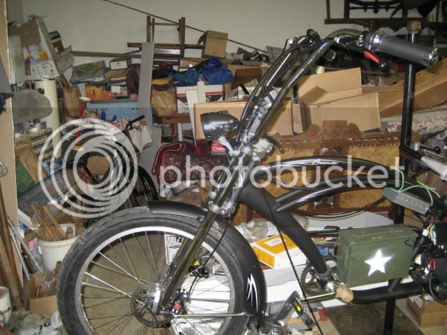
Ok, and here are the pics of it on the bike thus far:

CruiserHeadlightampIgnitionSwitch005_zps478135cb.jpg


CruiserHeadlightampIgnitionSwitch004_zps26a323aa.jpg


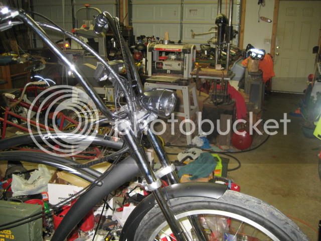
And the headlight is getting the Lyen $15 DC to DC converter treatment, and using the light accessory plug from the CA, I will have the headlight powered from the main pack with ease!

CruiserHeadlightampIgnitionSwitch003_zpsba8f4327.jpg


CruiserHeadlightampIgnitionSwitch002_zps6bda3baa.jpg


CruiserHeadlightampIgnitionSwitch001_zpsb3346c17.jpg
 
LI-ghtcycle said:
The really nice thing is it's just about 1 inch in diameter, so if you have an 1 & 1/8 size steer tube, you could remove the cap and star nut on top and put one of these switches in a nice natural spot!
Like this?
http://electricle.blogspot.com/2009/02/first-road-ride-about-6-miles.html
KeySwitchInStem.JPG

:) mine's not really a steer tube, but an extension made from a seattube upside down clamped around the steerer, but the same thing applies. Mine is mounted just using foam tape around the keyswitch and stuffed in there, but a much nicer cap could easily be made to mount it like that.
 
amberwolf said:
LI-ghtcycle said:
The really nice thing is it's just about 1 inch in diameter, so if you have an 1 & 1/8 size steer tube, you could remove the cap and star nut on top and put one of these switches in a nice natural spot!
Like this?
http://electricle.blogspot.com/2009/02/first-road-ride-about-6-miles.html


:) mine's not really a steer tube, but an extension made from a seattube upside down clamped around the steerer, but the same thing applies. Mine is mounted just using foam tape around the keyswitch and stuffed in there, but a much nicer cap could easily be made to mount it like that.

Great minds think alike eh? :wink:

I have done the same thing with a seat post tube to make the mast on my recumbent, just wish I had found this switch sooner, as the mast has a cap really only for show, and it would be much much cleaner looking with it mounted that way, I may get a second one to install on my recumbent similarly.

I have used some pretty typical keyed switches in the past, but the annoying part was half of them didn't capture the key when in the on position, so I would have a retaining strap of some sort to keep it from being lost, big hassle since I wanted the key to be there as an easy to reach off switch, so I am excited to test this one out!
 
Well, it looks like I will be trading in this motor for a hub motor, most likely one from JohninCR's "hub-monster" family, thinking the mid-monster, but I haven't completely fleshed out the way I will mount it, going to put up a drawing here soon to get some feed-back from everyone on the mount.

Unfortunately, I think the trike motor I had been using didn't show it's weakness like it would have on my recumbent due to it's superior lack of aerodynamic drag, and this bike is quite the opposite in that regard, so the motor really isn't performing half as good as I had hoped even at 60V, it's really not got the strength it should.

Sorry to get back so late with the up-dates, the Flu has been really nasty this year, and soon as I get over it I seem to get it again, doh!
 
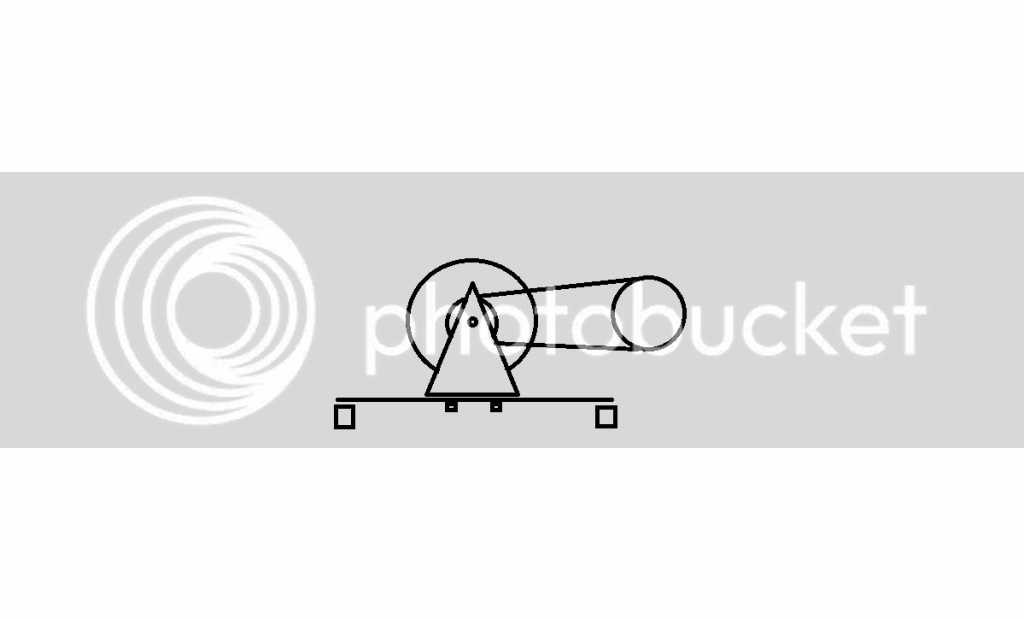
Ok, here is my new design to hold a hub motor in the same area of the frame of the bike as the current motor:

HubMotorMid-DriveCradleDesign_zps458a1feb.png


The plate that the cradle would sit on will have slots and 2 - 4 bolts along the bottom with captured nuts on the other side to allow you to simply loosen, get the desired tension, and then tighten them back up.

This should eliminate any need for a tensioner for the motor chain.

Thoughts?

Thanks!
 
LI-ghtcycle said:
The plate that the cradle would sit on will have slots and 2 - 4 bolts along the bottom with captured nuts on the other side to allow you to simply loosen, get the desired tension, and then tighten them back up.

This should eliminate any need for a tensioner for the motor chain.

Thoughts?
Only that that plate needs to be very stiff. I had a number of problems with my similarly-tensioned/mounted powerchair motor on CrazyBike2, when I used a 3/32" pretty hard steel plate, which was welded solidly across bottom of the tubing of the spread-out rear chainstays of the front frame, more than a wide handspan width where the dropouts would have been. I added another thickness of the same stuff, spot-welded thru around the areas it'd flex at and all around the edges, and it helped a lot--but it still flexed enough to *see* the chain sag a bit on the unloaded side. I think starting with 1/4" plate would have worked better. Or harder metal.
 
amberwolf said:
LI-ghtcycle said:
The plate that the cradle would sit on will have slots and 2 - 4 bolts along the bottom with captured nuts on the other side to allow you to simply loosen, get the desired tension, and then tighten them back up.

This should eliminate any need for a tensioner for the motor chain.

Thoughts?
Only that that plate needs to be very stiff. I had a number of problems with my similarly-tensioned/mounted powerchair motor on CrazyBike2, when I used a 3/32" pretty hard steel plate, which was welded solidly across bottom of the tubing of the spread-out rear chainstays of the front frame, more than a wide handspan width where the dropouts would have been. I added another thickness of the same stuff, spot-welded thru around the areas it'd flex at and all around the edges, and it helped a lot--but it still flexed enough to *see* the chain sag a bit on the unloaded side. I think starting with 1/4" plate would have worked better. Or harder metal.

Thanks AW!

I agree, and I should make a new drawing to better reflect the design, it's going to have those two horizontal square tubes a lot closer together, so it won't have that as much of a possibility, and depending on what I decide, now that I'm not as concerned about welding on this frame, I might just anchor that plate directly to the frame and that would give me a lot more flexibility, so that I can eliminate some of the space needed for the two horizontal tubes, giving me about 1 1/2 inches more vertical height to play with.

That would only require me to space out the two to four bolts onto either side of the motor plate, my main concern is getting a "cradle" that is of sufficient thickness of plate (I'm thinking 1/8" should be more than enough) and I can always skeletonize the pyramidal sides to take off some weight with out losing any strength.

I could always go straight up with a couple of rectangular pieces of tube, but that would probably be just as costly, and would require a gusset of some kind.

I want this a bit over-built so that you can add tons more power later if desired with out having to beef up the mount.
 
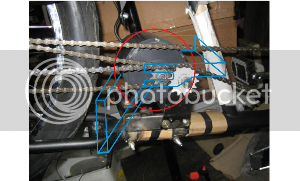
Ok, here is a more comprehensive picture, and more minimalist design. (the red circle represents the larger diameter mini-hub monster (it's only about 2" larger in diameter, but 2 inches shorter length!)

CruiserMini-MonsterHubMotorMount1_zps7ec3c4af.png


One nice feature of this design is that I can hopefully eliminate the need for a chain tensioner (for the 2500W and lower power zone) due to the lack of flex that should occur with a ridged grooved plate construction that will stiffen it up considerably on the flat areas, and if it really needs it, it can be replaced with tube in place of flat bar. The ease of mounting is as simple as removing the rear tire, sliding in the motor, and then replacing the tire. This will only give about 1 - 2 inches of play to tension the chain, but it shouldn't really be an issue with half links available if needed.

It may require more "boxing" with a third set of "arms" to beef up the triangle of the mount between the motor and seat post, if it proves to be too weak, I want to keep weight down, but I want it pretty much set up so that if a prospective customer so desired, they could bolt in the larger Hub-Monster and go bat-crazy with power, but with the mini-monster, it makes a nice starting point (and yes, I know the mount will need larger slots to accommodate the hub-monster, but if you're going that far, what's a little widening of the slots right? 8) ) but be capable of much more.

Thoughts?

Thanks!
 
Less is more AFAIC, and this one seems stronger than the first. As long as it's rigid enough, and you like the look of it, then that's what matters.

My vote would be to plan on a spring loaded idler instead of trying to avoid it. IME that's the route to the quietest chain. Bike hubs and bearings can't maintain a perfect alignment under the load an electric motor can put on the sprocket. An idler that guides the slack side of the chain into good alignment with the sprocket and prevents the slack side from dancing around makes a tremendous difference in noise, especially with it in contact with more sprocket teeth moving at a far greater velocity than on a pedal bike.
 
John in CR said:
Less is more AFAIC, and this one seems stronger than the first. As long as it's rigid enough, and you like the look of it, then that's what matters.

My vote would be to plan on a spring loaded idler instead of trying to avoid it. IME that's the route to the quietest chain. Bike hubs and bearings can't maintain a perfect alignment under the load an electric motor can put on the sprocket. An idler that guides the slack side of the chain into good alignment with the sprocket and prevents the slack side from dancing around makes a tremendous difference in noise, especially with it in contact with more sprocket teeth moving at a far greater velocity than on a pedal bike.

Thanks for you input John, I think you are right, if I start going higher powered, or experience chain chatter even at lower power (around 1200 Watts) I will be employing some form of tensioner, but I still like to have the ability to move the motor back and forth for to adjust chain tension initially.

It turns out that my motor might not be having as much problem as I thought, I haven't got it set up today, but I think tomorrow I will have time to try setting up the bike with out the CA (just shipped it back the Grin Technologies to have it looked at) and see if I get better performance.

The more I think about it, my current motor wasn't seeing half the wattage that the CA was displaying, and if it had, I know that the motor would have gotten at least a bit hot, as I know how my other identical motor/controller on my Recumbent runs, so I am going to give it a go tomorrow and see what I get!

I'm thinking there is a really good chance that either the CA or the controller might have been restricting the wattage more than I realized, I will double check the settings on my Lyen controller and see if it makes a difference, conversely I can just hook up my older CA to! In fact that should work great since I am using virtually the same sized wheel (outside diameter wise)!
 
LI-ghtcycle said:
The more I think about it, my current motor wasn't seeing half the wattage that the CA was displaying, and if it had, I know that the motor would have gotten at least a bit hot, as I know how my other identical motor/controller on my Recumbent runs, so I am going to give it a go tomorrow and see what I get!

I'm thinking there is a really good chance that either the CA or the controller might have been restricting the wattage more than I realized, I will double check the settings on my Lyen controller and see if it makes a difference, conversely I can just hook up my older CA to! In fact that should work great since I am using virtually the same sized wheel (outside diameter wise)!

If the CA displays a certain wattage, and it is accurately calibrated, then that means the system as a whole is pulling that power from the battery, and it has to be being used up somewhere--either as work moving the bike, or wasted as heat in inefficiencies, resistances, etc., in the motor, controller, and wires.

If the controller "restricts" the wattage via current limiting, then the CA would not show any higher wattage than the system then consumes; it would be lowered by that restriction. If the controller itself is heating up greatly when the motor is not, then something else is probably going on, perhaps iwth controller settings, but that would explain where some of the "lost" power is going. If it's not getting hot either, then it's not dissipating that lost power.

If nothing in the system is getting hot, and you are sure you're not actually using the power in moving the bike, and the CA is definitely calibrated and reading correctly, then I can't imagine where the power is going--those are the only things I can think of that could consume the power from the battery.
 
amberwolf said:
LI-ghtcycle said:
The more I think about it, my current motor wasn't seeing half the wattage that the CA was displaying, and if it had, I know that the motor would have gotten at least a bit hot, as I know how my other identical motor/controller on my Recumbent runs, so I am going to give it a go tomorrow and see what I get!

I'm thinking there is a really good chance that either the CA or the controller might have been restricting the wattage more than I realized, I will double check the settings on my Lyen controller and see if it makes a difference, conversely I can just hook up my older CA to! In fact that should work great since I am using virtually the same sized wheel (outside diameter wise)!

If the CA displays a certain wattage, and it is accurately calibrated, then that means the system as a whole is pulling that power from the battery, and it has to be being used up somewhere--either as work moving the bike, or wasted as heat in inefficiencies, resistances, etc., in the motor, controller, and wires.

If the controller "restricts" the wattage via current limiting, then the CA would not show any higher wattage than the system then consumes; it would be lowered by that restriction. If the controller itself is heating up greatly when the motor is not, then something else is probably going on, perhaps iwth controller settings, but that would explain where some of the "lost" power is going. If it's not getting hot either, then it's not dissipating that lost power.

If nothing in the system is getting hot, and you are sure you're not actually using the power in moving the bike, and the CA is definitely calibrated and reading correctly, then I can't imagine where the power is going--those are the only things I can think of that could consume the power from the battery.

In talking to someone at Grin Tech (Ebikes.ca) I forget his name, i was suggested that the R-Shunt value may have needed proper calibration to my Lyen controller, and I am using a V 2.3 my other CA is a V 2.23 or 2.25, doubt this would make that much difference, but maybe I need to double check the R-shunt value for each of two my controllers using this motor, perhaps I will get more accuracy there too.

It would really surprise me if the amount of wattage was accurate given how little the motor warmed up and how little power it put out.

The real clincher was when I returned after the test ride and upon attempting to reset the values, it started showing bizarre characters that make no sense, I will test with out a CA first and go from there.
 
If the shunt setting in the CA isn't calibrated to your actual shunt being used, the readings could be off by huge amounts. Let's say the CA is set to 1mohm for shunt value by default, but your controller's shunt is 2mohm--that's a factor of 2! double or half what it should read.

So if the shunt isn't calibrated for your controller (or other shunt), all amp and watt readings are invalid, as it is unknown by what factor they are off. Voltages and distance readings are the only things you can use until that's fixed.


Wierd characters on teh screen is something else entirely, and might be either a humidity or moisture issue, or an actual problem with the CA.
 
Wow! Been almost 2 yrs since I up-dated this build! :shock:

However, I am back at it! :D

I am currently holding in my hands a V3 Hubzilla (Cromotor)Hubmotor that I will use as Mid-Drive, and I am thinking I will attach it with a similar designed cradle to the Stoke Monkey system as it allows a lot of fine tuning of the chain alignment, and being one of the best 48V hub motors out there designed to be very efficient (91%) and I will be installing one on my Vision R-40 Recumbent too after finishing this one, as I really like the ability of a big beefy hub motor to soak heat while climbing hills, and if a 9C (amped bikes) hub motor can climb these monster hills in Oregon City with out getting warm, I am sure that the V3 will do the same at even greater speed. 8)

I need to get the bike to the shop (Al at Classic Cycles will be giving me space to work on it soon!) so I can finally complete a "flag ship" E-Bike that I planed so long ago! :wink:
 
Thanks Rassy!

How is your 'bent trike running? I will have to take some pointers on how you mounted your hub! 8)

I am really excited to see this bike in motion! I will be running it with a 48V 20 AH LiFePo4 A123 Prismatic Battery, as I have gotten away from the LiPo just because I prefer to have a more "plug & play" battery that is easier to maintain and requires less work to install/build.

The Vision R-40 has been a dream, but I am going to slim it down and remove the panier cargo pods on the back and just use the trailer when needed so I can keep it as close to it's original handling as possible. My biggest obstacle has been the growing junk piles around & in the garage (got a plan to get rid of them, just need permission & motivation to make room to work!)

I will be glad to have a nice low KV (9.3) hub motor to allow me to use bicycle chain again as the smaller chain just isn't up to the task at this long of a run, so single speed BMX chain and cogs (no freewheel needed with the NuVinci) will be the order of the day. :)
 
Ok, so I need some Molex Crimpers, but I can't see buying the racheting style as I am just using them occasionally, in this case, it will be attaching the Hall Wire connectors, and I would love to get some that also have wire strippers, since I don't have any that go down to the small size of the typical Lyen/Keywin (24 - 30G?) and I don't want to have to take an hour with standard pliers when the right tool can do it in minutes.

I have seen a few offerings on Ebay and Amazon, but so many seem to lack wire size info, and I wan't to make sure they are able to work for these very small connectors.

Any recommendations?

Here are a few potential candidates I found so far ...

http://www.ebay.com/itm/like/331632835270?ul_noapp=true&chn=ps&lpid=82

http://www.amazon.com/Waldom-Electr...lex+crimping+tool&refinements=p_72:2661618011

I'm leaning towards the non-racheting style, and the fact that the Amazon Waldom Electronics Tool comes with wire strippers seems to be a pretty nice bonus, but I am afraid I am buying junk? :roll:
 
Ok-

It never happened unless there are PICS!!


Al at Classic Cycles in Oregon City has moved up the hill pretty close to my house (2 - 3 miles away!) and has made a space for me to work in his shop.

I am in the process of building one of my more "off the shelf" builds yet!


Excuse the crude MS Paint drawing, but more or less, I have discovered that the standard 3 pc BMX crank sets that are typically on the less expensive side are PERFECT to act as a cradle for the Hubzilla (Cromotor V3) as I will not be using a "drop out" per-se, but more of a captured slot milled at the local machine shop to be a snug fit for the Cromotor's Axle flats.

These will be done using the good ole' BMX Stem as vertical to horizontal clamp (similar to how some RC builds have done to use a BB as jackshaft) and from there we will make a custom clamp to fit our purposes as seen in the drawing above.

The real beauty of using the Steel BMX Spindle & Cranks is the strength and ease of sourcing the parts. Other than having to partially fill the old pedal hole and mill a precise fit for the Hubzilla axle, the crank arms are near perfect fit! (only 1/32 to 1/16 gap when lined up with the Hub)

I will be visiting City Machine to have the work done hopefully in the next few days.

This will be my first truly powerful E-Bike set-up, I will be running the Hubzilla with 18S, 12 AH Turnigy Nanotech 25-50 C LiPo, Lyen Controller so, 70V, and around 50 - 60 Amps and shoot for a top speed of 50 - 60 MPH! :D

Time to buy some more 10G Silicon Wire!! :twisted:
 
More ugly MS Paint pics! :p

These are just the rough ideas of how I would like to arrange the batteries in a semi-faux ICE style, just to make them look like they belong there instead of just a weird random box.


(On top, the controller, the middle box with the keyed switch slot will house most of the excess wires, however, I will leave the wires coming off of the Lipo bricks exposed for the most part,and with everything so close together, it should make it very clean looking otherwise, only minimal wires/cables going to the bars. 8) )
 
Talked to the machinist, going to have to make some changes, but keeping the over-all design.

Most likely will be milling the ends of the cranks where the pedals would attach and just TIG welding a new piece to them be machined to a snug fit with the axle, with allowing for the wires on the non-drive side, so it will have a 1 x 1/4 x 3/8" gap for the wires to pass through, but otherwise still an enclosed end much like a "box end" wrench.


I've tried to capture that the LH arm of the Hub Mount has a thicker width so that about a 1/4" notch is cut out to allow for the wiring.

I can hardly wait to get this done and start the wiring phase!

It's been brought to my attention that at higher volts that I will need to brace the pivot of the mount, so I am planning on trying things at about 12s (LiPo) to start with, and I will eventually work up to 18s and probably add a go-kart tie-rod to keep it from sliding forward and breaking the chain under power.

I'm hoping that this one will be sufficient:

s-l1600.jpg


http://www.ebay.com/itm/8-Aluminum-...t-for-Go-Kart-Racing-Cart-Parts-/141161372567
 
Well, since I started on my design for the Vision R-40 (E), I decided to incorporate the principals of that design for this build too. My partner in this project wanted a simpler design with less machining required, so here is the latest:

(for details on the mount, check out my other build with similar design https://endless-sphere.com/forums/viewtopic.php?f=28&t=75247&p=1139296#p1139296)

This drawing really isn't a very good representation of what I want yet, the back side of the mount (might be putting a battery there too) is really odd looking, not sure what I will do to clean it up and make it look more like it "belongs" there instead of a "flying box" as most battery packs are square, that's how they usually end up, wanting to avoid that look.

 
Well, progress is progress, perhaps I just need a more little help from "Mokey" (Smokey with out the "S") and things would be different!


Mokey is the official "guard kitty" at Classic Cycles, the moment someone opens the front door of the shop, she goes to "attack" them with cuteness!

That, and to see if they brought a new box for her to hide out in!

(she was left behind one day and the owner never made it back, but she's very happy and friendly, evens gets visits from "Maddy" the dog from the dog grooming shop next door :D )

And if you spied something "Surly" on the floor in the second pic, you're right!


Got the 22T Track Cog today, and with a little spacer in the back, should allow it to give us good alignment!

Clamps came in today too, unfortunately, I screwed up thinking I was ordering PIPE OD sized, and got TUBE (true OD size) so instead of 1" pipe, it fits 1" tube, so I ordered another set at 1 1/2" size, oh well, free shipping, so only a $16 mistake, and the 1" will fit a bike with a 26 mm seat tube, so maybe this means I need to mount something to my 700c Hybrid in the future. :wink:
 
Well, it turns out I needed to place the motor a bit higher to avoid conflicting with the pedals, as a bonus, the Hub Arm is now a simpler design (which is especially good on the prototype, it doesn't have to be pretty, just work).


A view of how the motor chain line will pass between the mounting blocks -


Finally got to cut some metal! 8)

I was about to go and make an arm with some steel I have lying around when I got the green light to go with Aluminum instead, and wow am I glad I did!

Locally, SMI Metals, a wholesale company has just opened a store to the public, and not only are they very reasonably priced, they are half-way between home and the bike shop! (about 1 - 2 miles from home :mrgreen: )

They had just what I was looking for, 6061 Aluminum accurately machined, and since my Hub Arms fit in a 12 x 12 x 1/4" square, even cut me two pieces from separate "tiles" to give me identical 6" wide by 12" long pieces, making my life MUCH easier as I am making the prototypes in the garage with a drill press, and some hand held power tools (My multi-tool from Harbor Freight is quite amazing cutting 1/4" or thinner aluminum, like having the accuracy of using a hack saw, but cutting 3x as fast, not as fast as an angle grinder, but extremely accurate & removing minimal material, barely heating saw or metal being cut) , belt sander and files.

Once we have a working design we like, we'll go visit the machine shop again.


Back
Top