Inductance What is it what does it do? Collosus has 8uH!

Hey Ladies,

the problem is not the inductance, it is not the resistence, the pwm frequency or the timing.

The problem is all together!

low resistance and low inductance, slow pwm = high current flow
this together with the wrong timing and you need a new controller.

The question is: what can we do first to don`t kill the controllers but get a better performance out of the motor?
My comment: a adjustable timing brings us to a 90% solution?
 
c_a said:
Hey Ladies,

yes ? :mrgreen:

c_a said:
the problem is not the inductance, it is not the resistence, the pwm frequency or the timing.

The problem is all together!

I've been thinking about circuit's 3uH motor problem, I mean, such a high ripple current at such a low maximum current, there has to be something wrong....

Lets see which things we can change given a certain motor topology... The problems seems to be that

slope_to_useful = (dI/dt) / I

is too high. Here dI/dt is the slope of the ripple current, this is divided by the (wanted usefull) current I. And this ratio has to be as low as possible.

dI/dt is from the inductor and is equal to V/L .

V is proportional to the motor's back-emf. The bck_emf is proportional to magnetic field strength, stator tooth area, motor speed and the
number of windings N. Since the mechanical bits are all given (unchangeable) and we can only change the amount of windings N, here all we need to use is:

V is proportional to N.

In the same way for the inductance L, this depends on all kinds of factor which we cannot change, and the amount of windings squared. Therefore

L is proportional to N^2

I is the current we put in. We are basically free to choose it's value but at a certain point the stator will saturate. This happens for a certain amount
of AmpTurns. This max 'AmpTurns' is again a property of the motor design and material used, unchangable. Using this:

I = AmpTurns / N

Substituting all this in the first equation (=~ means: is proportional to):

slope_to_usefull = (dI/dt) / I =~ (V/L) / I =~ (N / N^2) * (N/AmpTurns) = 1/ AmpTurns

I just make this up as I go along so if I go wrong somewhere let me know but I got the idea that

slope_to_usefull =~ 1 / AmpTurns

and that the amount of AmpTurns should be as high as possible. AmpTurns is bound to a maximum as above a certain value the core
saturates. To keep the slope_to_usefull ratio in check the motor should be operated as close as possible to its AmpTurns maximum.
Also, if the stator design is not very good (like thin stator teeth for instance) the AmpTurns_max is low and the motor has a high slope_to_usefull
ratio. It can still be run fine but it needs a high PWM to keep the ripple in check.....

B!tch is that the resistive losses are proportional to AmpTurns squared

P_loss = I^2 * R

R is the winding resistance, it's proportional to wire lenght and wire cross section area

R =~ length / wire_area

length is proportional to the amount of windings N. Wire_area is proportional to the area allowed by the stator tooth design divided by N. The available
area between stator teets is a motor property which we cannot change so

R =~ N / (1/N) = N^2

Therefore

P_loss =~ (AmpTurns/N)^2 * N^2 =~ AmpTurns^2.

So the happy conclusion :( is:

Just increase your resistive losses and your motor controller will be fine !

life sucks :(
 
Lebowski, that looks like a good idea for a very short pulse, but it doesn't seem to me that easy to have a driver+MOSFET combo that handles "useful" power and is able to switch (latency included) in around 33ns. Just the uC itself will probably take some 50% of that time to switch it's output pin.
 
The problem appears to be current ripple.

How does timing eliminate this problem?

Timing improves PWM resolution.

Better resolution will allow injecting a tiny current into the motor without blowing the FETs in the form of short pulses, but the average motor current will not be useful.

Increasing the pulse width to put useful power into the motor will lead to high current pulses. Ripple is not solved.
 
circuit said:
Ipp = 70V/(16kHz*2*6µH) = 365A; Ip = ±182A; Irms = 105A.
If you are using your previous case, with EMF of half the battery voltage, then you are off with a factor of 2. Voltage to cause ripple would be 35V. The RMS current would be 50A-55A, not 108A.

Are you sure that half the bridge is conducting through the body diodes? I was assuming it was switching on the upper FETs when the lower wasn't conducting, like a synchronous buck converter.
 
c_a said:
Hey Ladies,

the problem is not the inductance, it is not the resistence, the pwm frequency or the timing.

The problem is all together!

low resistance and low inductance, slow pwm = high current flow
this together with the wrong timing and you need a new controller.

The question is: what can we do first to don`t kill the controllers but get a better performance out of the motor?
My comment: a adjustable timing brings us to a 90% solution?
I have played with timing. And while having my LC meter hooked up the inductance varies from ~10uH in one spot to 8uH in the worst spot. I am 100% sure you can't solve this with timing with the current mosfets available. As better mosfets become available then the mosfet it self will be the solution.
But to make it short Yes all three PWM, inductance, and resistance are the problem.
BUT as the spread sheet points out changing the resistance has VERY LITTLE effect on the current. And you want the lowest possible resistance to make it as efficient as possible. So Then we have 2 variables left the PWM which is limited buy current fet technology and inductance.
What we then do is choose do we wind it for lower KV and up the volts?
Or do we add external inductors?
Once we make our decision then we select the best possible mosfet for the voltage and once we have that we select the PWM frequency.
Then if we added external inductors we can run it for a while and slowly remove them to see what the lowest inductance we can really run is!
 
c_a said:
The question is: what can we do first to don`t kill the controllers but get a better performance out of the motor?
My comment: a adjustable timing brings us to a 90% solution?

I'm not sure what you mean with timing, but I think you can do some "magic" with software. You would not have a fixed PWM frequency, you would just keep the average number of switches per second within some limits. Then drive/short/release the phases in a pattern which would give the best possible waveform at the current RPM and throttle. You could maybe switch fast at parts of the envelope where it is needed. At other parts of the envelope you could just short the windings for a relative long time, and wait for currents to fall.

Maybe something similar to Roman Blacks one-bit-audio
http://www.romanblack.com/picsound.htm

Maybe use a switching frequency inversely proportional to working current? so that the ripple to working current ratio always is the same? at low working current levels the switching losses are small even if frequency is high, so there won't be a big penalty of switching a lot. Maybe there would even be a net gain, since the ripple would get lower, which would reduce conduction losses.
 
As I see it, all of this as simply caused by not enough reaction speed from the electronics (in the loop sense current -> turn-off MOSFETs). Maybe we need to solve that in another way: by temporarily inserting a resistor in series to "hard limit" the current in situations where the BEMF isn't enough. This can be done with an extra switch, setup as to bypass that resistor. So, if we can tolerate let's say up to 300A on a 72V system, our resistor would be 0.24 Ohm (and maybe some 3..4W). The controller starts with the wall bypass switch OFF. As it makes the first PWM cycle on the (very low inductance) motor, the current ramps up very fast and hits the 300A wall; some tiny time later the controller detects it has hit the wall and turns the MOSFETs OFF ending the PWM cycle. This will be repeated a "few" more cycles until the motor starts spinning and BEMF brings current down; the controller detects that the wall is no longer being hit and turns on the wall resistor bypass (the turbo turns ON, lol). When the current hits the wall again, there will be a PWM cycle or 2 where it will be big, but I guess the controller and motor won't have problems handling "*once*" a big amount of amps for just the few us the "wall hit" detection takes - until the controller disables the resistor bypass again.
There are problems to be solved in this, but it's a suggestion. Comments, ideas, rotten tomatoes?...
 
Njay said:
Maybe we need to solve that in another way: by temporarily inserting a resistor in series to "hard limit" the current in situations where the BEMF isn't enough.

That's all well and good in theory... until you do I^2*R and realize that 300A through a 0.24 ohm resistor is 21.6 kW. It's not practical to limit the current using resistance, not to mention inefficient too. Has to be done via inductance or increasing PWM rate.
 
Hummm, I was thinking it's not 21KW, once you use a lower PWM frequency at startup and your controller keeps detecting "wall hit" and turning off the MOSFETs for the rest of the PWM cycle period, and that is not a situation being kept for a long time. But in fact doing the math, even for a 1 KHz PWM frequency with 2us turn-off response time it's still ~43W. :shock:

Ok, not to mention the average current delivered to the motor! Dumb idea.

But still, maybe a smaller resistance can have the effect of lowering ramp up time. Let me look for bigmoose's spreadsheet.
 
Njay said:
Hummm, I was thinking it's not 21KW, once you use a lower PWM frequency at startup and your controller keeps detecting "wall hit" and turning off the MOSFETs for the rest of the PWM cycle period, and that is not a situation being kept for a long time. But in fact doing the math, even for a 1 KHz PWM frequency with 2us turn-off response time it's still ~43W. :shock:

The other issue with this general premise - that we don't need to limit the current, we just need to have the controller react very fast to shut down PWM - is that you'll end up with a very low duty cycle in this low speed starting-from-stop regime, which in turn means low torque and low power output. You end up basically kneecapping the potential of your high-power motor at the low speeds when it should really shine and put out loads of torque. It'd be like having a V8 in your car, but half of the cylinders are disabled until you're going 55 MPH. :)

I still think it's a good idea as a fool-proof safety feature to have the controller shut down fast and avoid blowing itself up. If (when) I have the time to build one, it'll definitely have this feature. But the the motor still needs to be "driveable" on it's own.
 
Yeap, it's all that.

I was playing with the spreadsheet and even for colossus it doesn't seem to have a current raise speed "that" high. I guess the current controllers' problem really is measuring battery current instead of phase current and/or not having a per PWM-cycle current limiting.
 
Agreed, the required inductance is going to be a lot lower for a "smart" controller with proper sensing and a fast reaction time than for a "dumb" controller that's slow and relies on averages.
 
Alan B said:
This motor is 8-10uH and what resistance?
Its the motor A resistance in the spread sheet a couple pages back.
 
rhitee05 said:
I still think it's a good idea as a fool-proof safety feature to have the controller shut down fast and avoid blowing itself up. If (when) I have the time to build one, it'll definitely have this feature. But the the motor still needs to be "driveable" on it's own.
This is why we chose a fet driver with a SD pin on it!!! As well the controller has a SD pin and the dspic30f is quite fast!!!
 
If you have an infinitely fast reacting controller running at 16khz, and the L/R time constant is WAY shorter than the 62 uS period of the controller you still only get to put one pulse into the motor every 62uS, but the current will rise quickly forcing a quick cutoff, and decay quickly and the average current will be very low.

Better FETs don't fix the problem. Unless you can RAISE the PWM frequency. Or lower the circuit resistance (which is mostly NOT the FET). Or raise the inductance. Or LOWER the supply voltage, matching the supply to the motor.
 
Alan B said:
If you have an infinitely fast reacting controller running at 16khz, and the L/R time constant is WAY shorter than the 62 uS period of the controller you still only get to put one pulse into the motor every 62uS, but the current will rise quickly forcing a quick cutoff, and decay quickly and the average current will be very low.

Better FETs don't fix the problem. Unless you can RAISE the PWM frequency. Or lower the circuit resistance (which is mostly NOT the FET). Or raise the inductance. Or LOWER the supply voltage, matching the supply to the motor.
What i am saying is if the fets can turn on and off faster and have a lower rdson then they will help.
 
Alan's point is the same one I made a short while ago: even if you have a) fast current measurement and b) the ability to shut the FETs down quickly, it will still be really hard to put significant power into a motor if the rate of current rise is really fast, because the FETs will always be shutting down and the duty cycle will be low. Slowing the rate of rise will help you much more than lowering the Rdson a little bit.

Arlo1 said:
What i am saying is if the fets can turn on and off faster and have a lower rdson then they will help.

Choose one, you can't have both. Low Rdson requires a large die, which makes the capacitance large and switching slow. Fast switching requires lower capacitance and a smaller die, which means higher Rdson. It's a tradeoff. Technology will gradually push both curves downward, but the tradeoff between the two is basic physics and isn't going to change.
 
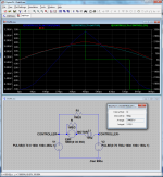
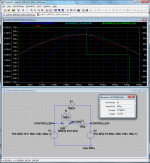
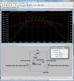
Some of you seem to think that more inductance is only better. I don't agree. I made these simulations to prove my point.

Imagine if the C80-100 with a kV of 136 RPM/V would have 100uH phase-phase inductance. Then it would have problems making power at high RPMs, even with 70V battery voltage.

Take a look at the following graphs:
file.php

batt70V_EMF35V_100uH_555Hz.PNG
At 4760 RPM (half max) and 35V EMF, max power would be in the area of 3.5kW.

file.php

batt70V_EMF52V5_100uH_833Hz.PNG
At 7140 RPM and 52.5V EMF, max power would be in the area of 2.8kW. Power is actually lower than at 4760RPM, opposite to what you would expect, since higher RPM should give more power.

As you can see in these graphs, the rise rate is simply too slow to be able to put high enough currents through the windings. I'm sure you could tune it a bit by using a little more advance than the 30° used here, and by using a little longer ON-time, but not by a whole lot.
 
your simulation only shows the high-frequency PWM ripple of the inductor current, not the low-frequency
(same frequency as back-emf) power delivering current which is superimposed on this.
 
Take another look. In the first pic, the motor EMF is a half period of a 35V sine with 555Hz frequency. Since the motor has 7 pole pairs, that corresponds to a speed of 60*555/7 = 4760 RPM. And at 4760 RPM it produces 4760 / 136 = 35V. I calculated this stuff before simulating to make it realistic.

The drive voltage is not PWM:ing at all, or put in other words, has 100% duty for the first 450us, and 0% duty for the rest of the period. I was playing with the values to make the current have a sine-like shape with the highest peak possible. The 100uH inductor is just so slow that PWM:ing isn't usefull, it would make the current rise even slower.
 
Lets change the inductance to 10uH. Now we need to PWM. With 46% duty during 650us of 900us we get 6.5kW. Current ripple is about 100A. Peak current is 380A, and average is about 250A.
file.php

batt70V_EMF35V_10uH_555Hz.PNG

Note that I had to play a lot with the values to get shape in this graph. If PWM:ing during the whole period, the current will rise a lot at the end. And that may be the reason why "dumb" controllers blow up. They simply have no control of whats going on. If you increase the advance just a few us, or increase the duty just a few %, the average current will be a lot higher than above, and the peaks will be past saturation of the iron.
 
With no motor series winding resistance the L/R would seem to be incorrect..

If you want to get the added inductance out of the commutation, so the inductance doesn't affect the timing, then separate the voltage down conversion PWM function from the commutation and don't use extra inductance on the motor.

This has been mentioned before, essentially a low KV motor is a low Voltage (and high current) motor. So you use a variable buck regulator BEFORE the Commutation FETs. This way the inductor (of which there is only one) doesn't have to dump its energy at the edge of every commutation cycle, and the low voltage/high current the motor needs is generated ahead of the commutation FETs. The commutation FETs don't need to do PWM at all then. The PWM is done in the buck converter.
 
Alan B said:
With no motor series winding resistance the L/R would seem to be incorrect..
The R doesn't change things a lot. In the 100uH case the average current will be lower. In the 10uH case the duty cycle needs to be a bit higher to get the same power.


Alan B said:
If you want to get the added inductance out of the commutation, so the inductance doesn't affect the timing, then separate the voltage down conversion PWM function from the commutation and don't use extra inductance on the motor.

This has been mentioned before, essentially a low KV motor is a low Voltage (and high current) motor. So you use a variable buck regulator BEFORE the Commutation FETs. This way the inductor (of which there is only one) doesn't have to dump its energy at the edge of every commutation cycle, and the low voltage/high current the motor needs is generated ahead of the commutation FETs. The commutation FETs don't need to do PWM at all then. The PWM is done in the buck converter.
This is a good idea. I suggested it in another thread. I think this is the way to go for low inductance motors.
 
Back
Top