Inductance What is it what does it do? Collosus has 8uH!

Alan B said:
With no motor series winding resistance the L/R would seem to be incorrect..
bearing said:
The R doesn't change things a lot. In the 100uH case the average current will be lower. In the 10uH case the duty cycle needs to be a bit higher to get the same power.

Alan is correct, the R does matter. It might not make a huge difference, but it does matter. I believe LTSpice assumes 1 mohm of series resistance for an inductor, wheras the real spec for the CA80-100 is something like 17 mohm.

Let me be clear - your basic point is valid. You can't really have a high-inductance, high-RPM motor because the short commutation time doesn't let the current reach steady-state. However, a high-inductance motor necessarily requires high turn-count which means a slower motor. That brings me to the fundamental flaw in your example. If you re-wound a CA80-100 to have 100 uH phase inductance, then it wouldn't be a 136 RPM/V motor any more. Higher inductance means more turns, which means a slower motor with a lower Kv. It's not a valid case to do a "what if" by changing one variable without the other.

The only exception to the inductance-Kv link is when you start adding external inductors, which is why that really should only be a last resort. Your point might be true in the sense that if Arlo makes his motor controllable with external inductors, it might limit how much power he can get at high RPMs.
 
Come on. I know what I'm doing. I was only putting in the essential stuff to make the point clear. I wasn't expecting people to be nit picking on stuff I left out on purpose.

People are crying about low inductance motors. I'm trying to say that motors need low inductance to be able to make power in the first place. In my example with 100uH, max power was 3.5kW. That also means that with 10uH, max power is 35kW.

I'm also illustrating that the ripple current with 10uH, 70V and 20kHz switching isn't super bad.

High power motors has low inductance, thats just a law of nature. If controllers are blowing up, then they have bad software, and/or they have bad power electronics design.
 
bearing said:
Come on. I know what I'm doing. I was only putting in the essential stuff to make the point clear. I wasn't expecting people to be nit picking on stuff I left out on purpose.

People are crying about low inductance motors. I'm trying to say that motors need low inductance to be able to make power in the first place. In my example with 100uH, max power was 3.5kW. That also means that with 10uH, max power is 35kW.

I'm also illustrating that the ripple current with 10uH, 70V and 20kHz switching isn't super bad.

High power motors has low inductance, thats just a law of nature. If controllers are blowing up, then they have bad software, and/or they have bad power electronics design.
There is something WAY WAY off with you calculations, Unless you have used a stupid low voltage for the calculations.
I have made over 6.5 HP at the rear wheel with a 255uH inductance motor! Im going back to look again.
 
bearing said:
I was only putting in the essential stuff to make the point clear. I wasn't expecting people to be nit picking on stuff I left out on purpose.

Excessive simplicity only makes the waters muddier unless you explain exactly what factors you're neglecting and why. For example, 17 mohm of resistance is a little over 4 V at 250 A, which is more than 10% of the BEMF at this speed. That's significant and will make a difference in the current.

I repeat: your 100 uH example shown is not valid. If you re-wound the motor to have 100 uH inductance, it would be something like 136/sqrt(10) = 43 RPM/V. That makes a difference! I was trying to be clear that I got the fundamental point you're trying to make, just that you chose a poor example. High inductance will limit power at high RPMs

bearing said:
I'm trying to say that motors need low inductance to be able to make power in the first place.

That's flawed logic and wrong. What you can't have is a high-inductance, high-speed motor. You can have a low-inductance, high-speed motor that makes tons of power. You can also have a high-inductance, low-speed motor that makes an equal amount of power. It's easier to design a high-speed motor because that means lower current for a given power output, but both are possible. The high-speed motor is harder to control, though.

bearing said:
I'm also illustrating that the ripple current with 10uH, 70V and 20kHz switching isn't super bad.

I'd beg to differ. It looks like you have about 100-120 A of current ripple on top of ~300 A average current (in the flat region). I think 30% current ripple is pretty significant, and your example is 46% duty at half-speed. Try the simulation with higher throttle at low speed and I think you'll get a much higher number.

bearing said:
If controllers are blowing up, then they have bad software, and/or they have bad power electronics design.

If you wrecked the suspension of your minivan driving off-road, would you say that it was poorly designed or would you recognize that it just wasn't designed to do that?
 
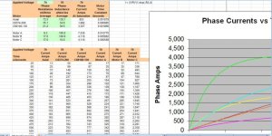
So here I set up the spread sheet to show battery voltage at 70v and I made motor A colossus with 100uH inductance and 9.3 mohms resistance which is what it is when I mesured it, Motor B a turnigy 80-100 with 100uH inductance and 17mohms resistance and motor C a turnigy 80-100 with 10uH and 17mohms.

Now one thing to point out is I have a small colossus which is the same as the turnigy 80-100 and mine is would for 75 kv and it has ~45uH so a 138 kv is going to be around 12.5uH (That explains whay luke could never get his twin tunigy set up to last).
 

Attachments

  • Capture 80-100 (800 x 401).jpg
    Capture 80-100 (800 x 401).jpg
    59.5 KB · Views: 1,598
rhitee05 said:
You can have a low-inductance, high-speed motor that makes tons of power. You can also have a high-inductance, low-speed motor that makes an equal amount of power.

This carries with it the implicit assumption that the voltage supply is constant/limited.

if you double the speed of a high induction motor:
- the back emf will double -> the part of your voltage supply that accounts for this must double
- if you want double the power then for the same current amplitude you also need to double the 'overvoltage', the extra voltage above the doubled back-emf
- for the same power you can keep the overvoltage the same, the current will half
 
So colossus is a 20 magnet motor and from that I figure we have 375uS to push amps into a phase on one side of the sine wave at 8000 RPM! This shows even with 100uH we have lots of time to push power into a phase at 8000 rpm which is probably higher then we need to spin it!

My math is 20magnets x 8000rpm = 160,000 magnets passing a stator tooth per rpm at 8000 rpm /60 = 2666.6666 mags per second 1/2666.666 = .000375 seconds per magnet!
 
Arlo1 said:
There is something WAY WAY off with you calculations, Unless you have used a stupid low voltage for the calculations.
I have made over 6.5 HP at the rear wheel with a 255uH inductance motor! Im going back to look again.

Was it a hub motor?
A low RPM motor gives more time for the currents to rise in the windings.

It's the combination of RPM, polecount, inductance and voltage/current that determines how well it will work. I was using the 80-100 as an example, and changed the inductance independent of other things, which illustrates the effect of adding external inductance (or removing some of the internal inductance, if that was possible).

The spreadsheet doesn't seem to contradict my simulations. In my simulation the "applied voltage" was 70V in the beginning, which decreased to 35V as the EMF increased. Peak after 450us was 220A. With a constant 70V in the spreadsheet, it hits 220A after 325us, which seems right. My simulation would have showed the same thing if there was 0V EMF.

Also, regarding the resistance, as you can see, the difference in phase resistance between motor A and motor B has a minor effect on the current.

So colossus is a 20 magnet motor and from that I figure we have 375uS
One half wave is 375us, that is correct. But remember that the current have to have time to both rise and fall, so the time to apply current is about half of that.
In my example, one half wave period was 900us, but current (EDIT: Voltage, not current) was only applied for 450us, to make it able to fall to 0 in time for the next (negative) half cycle.
 
Bearing, your simulations are not telling the full story, you assume certain timing. Different timing of the
controller voltages w.r.t. the motor's backemf will give different results.

What about a phase difference between motor current and supplied voltage ? If we start with the
PWM while the motor's back-emf is still negative you'll get a higher voltage over the inductor
so a faster current rise. Kind of like in a petrol engine, the bang comes before TDC so the the
flame has time to heat the gas to build pressure...

I know for a fact it's possible to run a motor at a higher back-emf than the supply voltage :shock: and still
have it make (lots of) usefull mechanical power.
 
One other advantage of moving the PWM out of the motor commutation FETs and into a buck pre-regulator is the frequency would no longer be governed by the motor materials. The single inductor material can be optimized for a higher frequency and the frequency chosen independently of the motor characteristics.

It is also a bit easier to do synchronous regulation.

It also gives the option of making different types of regulators so voltage boost is also possible which separates the battery voltage from the top speed.

An interesting solution.
 
rhitee05 said:
bearing said:
I was only putting in the essential stuff to make the point clear. I wasn't expecting people to be nit picking on stuff I left out on purpose.

Excessive simplicity only makes the waters muddier unless you explain exactly what factors you're neglecting and why. For example, 17 mohm of resistance is a little over 4 V at 250 A, which is more than 10% of the BEMF at this speed. That's significant and will make a difference in the current.

I repeat: your 100 uH example shown is not valid. If you re-wound the motor to have 100 uH inductance, it would be something like 136/sqrt(10) = 43 RPM/V. That makes a difference! I was trying to be clear that I got the fundamental point you're trying to make, just that you chose a poor example. High inductance will limit power at high RPMs

One of the reasons behind that post was simply to illustrate that adding inductance may not be a good idea. I was not "rewinding" without changing kV. If you want, I can link you to a post from the past where I was informing someone about inductance and kV. And now you are trying to lecture me about something I already know.

It was never intended to be accurate. It was just a super rough simulation to show the effects of inductance on a motor. Look at the wording I used "max power would be in the area of 3.5kW", by using "in the area of" I was trying to say +-50% or so. I have a hard time trying to explain myself in this foreign language to me, so I think this is the best I can do.

rhitee05 said:
bearing said:
I'm trying to say that motors need low inductance to be able to make power in the first place.

That's flawed logic and wrong. What you can't have is a high-inductance, high-speed motor. You can have a low-inductance, high-speed motor that makes tons of power. You can also have a high-inductance, low-speed motor that makes an equal amount of power. It's easier to design a high-speed motor because that means lower current for a given power output, but both are possible. The high-speed motor is harder to control, though.
OK, change high power in that quote, to "high power density". Do you agree with me now?

rhitee05 said:
Try the simulation with higher throttle at low speed and I think you'll get a much higher number.
Wrong. Highest ripple is at 50% duty.

rhitee05 said:
bearing said:
If controllers are blowing up, then they have bad software, and/or they have bad power electronics design.

If you wrecked the suspension of your minivan driving off-road, would you say that it was poorly designed or would you recognize that it just wasn't designed to do that?
OK, I think I need to express myself a little more humble, because it seems my posts are effective flamebites.
You are right, the controllers aren't designed for the motors they are used on. It seems there aren't any controllers on the market fit for the job. But that doesn't make my statement wrong.
 
Alan B said:
It also gives the option of making different types of regulators so voltage boost is also possible which separates the battery voltage from the top speed.

An interesting solution.

My first controller was based on having a boost-converter in front of the controller for power regulation. It had a
control loop which measured/controlled the motor current by changing the PWM of the boost converter FET.
The 6 commutation FETS were switched without PWM.

I gave up on this method as the ESR of the boost converters cap has to be impossibly low.

Never considered a buck converter due to the inherent speed limit
 
Lebowski said:
Bearing, your simulations are not telling the full story, you assume certain timing. Different timing of the
controller voltages w.r.t. the motor's backemf will give different results.

What about a phase difference between motor current and supplied voltage ? If we start with the
PWM while the motor's back-emf is still negative you'll get a higher voltage over the inductor
so a faster current rise. Kind of like in a petrol engine, the bang comes before TDC so the the
flame has time to heat the gas to build pressure...

I know for a fact it's possible to run a motor at a higher back-emf than the supply voltage :shock: and still
have it make (lots of) usefull mechanical power.

This is something I didn't investigate a lot. I tried a few degrees extra advance, but didn't think the effect was strong enough to have a lot of difference. More advance causes some negative work, just as in the case of petrol engines. If you are right, it puts my posts to shame a bit. I did put a "disclaimer" at the end: "I'm sure you could tune it a bit by using a little more advance than the 30° used here, and by using a little longer ON-time, but not by a whole lot", if it matters.
 
Lebowski said:
...

My first controller was based on having a boost-converter in front of the controller for power regulation. It had a
control loop which measured/controlled the motor current by changing the PWM of the boost converter FET.
The 6 commutation FETS were switched without PWM.

I gave up on this method as the ESR of the boost converters cap has to be impossibly low.

Never considered a buck converter due to the inherent speed limit

Interesting on the boost cap ESR requirement. Boosting power is not easy.

Of course the buck converter is what we all use now, so the speed limit is what we have now. Just requires battery voltage to be chosen for max speed, or a transmission to shift gears to get higher speed.

If the goal is to drive a low inductance and resistance (so low voltage) motor, the buck conversion is what is needed. Back EMF growth / speed limiting should not be a problem.

It is also easy to configure your battery system to go from parallel to serial and double the voltage (a couple of diodes and an FET or several in parallel). If the motor controller is set up to work with both voltages this is a way to have the supply voltage not be so far out of range with respect to the back EMF. I think some systems used to do this, but haven't seen any lately.
 
bearing said:
One of the reasons behind that post was simply to illustrate that adding inductance may not be a good idea.

Ok, then we agree. There is definitely a point at which adding more external inductance will be counterproductive. But I think there is also an area where it can be beneficial, in the sense that being able to run a motor at 75% of it's potential is better than nothing. Like any band-aid solution, it's not ideal.

bearing said:
OK, change high power in that quote, to "high power density". Do you agree with me now?

I don't think that really makes a difference. I wasn't able to find a reference for this, but I believe the maximum theoretical (peak) power for a motor is basically a function of the air gap flux density and the copper volume. Substitute copper fill for copper volume and we're talking about power density. You can configure that copper in a variety of different ways, which will give different voltage/current/speed points for max power (and different inductances), but the max power will be the same in a strictly theoretical sense. It's not quite as clean-cut when you need to actually build the motor, but roughly the same. I'm fairly sure LFP has brought this point up before. As an example, I would cite the various 9C windings available: 10x6, 9x7, 7x9, etc. The basic motor design determines the maximum power (magnet strength, amp-turns to saturate stator, air gap, etc), and different windings just change the operating point at which that max power occurs. I would also point out that when the crazier members around here (Doctor Bass comes to mind) go for really high power, they tend to choose slower-wound motors (higher inductance) and higher voltage. They have discovered that higher voltage/lower current and higher inductance/lower current ripple make this a more attractive option.

bearing said:
Wrong. Highest ripple is at 50% duty.

Should have clarified that I just meant higher current and more rapid rate-of-rise. Agree that 50% duty gives maximum ripple.

bearing said:
You are right, the controllers aren't designed for the motors they are used on. It seems there aren't any controllers on the market fit for the job. But that doesn't make my statement wrong.

I don't mean to harp on this, but as an engineer it really does bother me when people conflate "bad design" or "doesn't work" with "not designed to do that." We can try and add safeguards to ensure that the device stays in it's intended operating area, but that adds cost (remember we're mostly talking about Chinese controllers) and users are crafty buggers. The smartest engineer is no match for the dumbest user. :)
 
The tricky thing with a two-stage buck-inverter design would be allowing the inductor current (of the buck) to remain constant. You don't want a point where none of the phases are drawing current, then there would be a big voltage spike as the inductor dumps into the bus cap. Probably what you'd want to do is what's called a 180-degree inverter. The regular 6-step kind are 120-degree inverters because each phase conducts 1/3 of the time and you have 2 switches on at any instant. In a 180-degree design, you have three switches on and each phase conducts 1/2 the time. It's sort of like a poor man's sinusoidal commutation. I think this would ensure that the DC bus current is more or less constant.

Such a design would be a little less efficient, just because it has two switching stages, but you could at least partially make that up in design optimization. Since the inverter FETs are now switching at a lower rate, you could use big, low-Rds FETs and not care about them switching slowly. For the input buck, you could choose a faster-switching FET and use a higher frequency to keep the inductor size reasonable - it would probably need to be an air-core inductor, as the required core size for a high-power controller would be LARGE to avoid saturating at a couple hundred amps.

A little more difficult, but you could also make it a buck-boost design and have the best of both worlds.
 
bearing said:
One half wave is 375us, that is correct. But remember that the current have to have time to both rise and fall, so the time to apply current is about half of that.
In my example, one half wave period was 900us, but current (EDIT: Voltage, not current) was only applied for 450us, to make it able to fall to 0 in time for the next (negative) half cycle.
So about 130 amps is max at 8000 rpm with my chart at 100uH! If you have 100v 130 amps thats not bad power at MAX rpm!
 
20mags = 750 uS =1.33 khz at 8000 rpm
Edit: 1.33 khz but i am looking at 1/2 the sine wave so thats why i am talking about 375 uS
 
Alan B said:
900 uS is 1.1 khz.
One half cycle of the EMF was 900us. One full cycle is 1.8ms, which is 555Hz, as I said. Voltage was applied for one half of the half cycle, 450us.

But I didn't play a lot with advancing the voltage back into the end of the previous (negative) cycle. Lebowski may have found a flaw in my arguments.

Arlo1 said:
So about 130 amps is max at 8000 rpm with my chart at 100uH! If you have 100v 130 amps thats not bad power at MAX rpm!

A 130amps peak with a sine-like slope will have an effective current of 71%. And the motor voltage is also sine-like, so the effective voltage is 71%. So, the effective power is half the product of the peaks, just like when you calculate with grid voltage. In my example, the peaks were 35V and about 200A. 35V * 200A / = 3.5kW.

Remember also, that at max RPM the EMF will rise to the same voltage as the battery voltage. This will decrease the "applied voltage" to zero. The current cant rise as fast as in your shart when it is spinning at max RPM. But with some extra advance it may. It may rise past 130A. I haven't looked into that.
 
rhitee05 said:
I believe the maximum theoretical (peak) power for a motor is basically a function of the air gap flux density and the copper volume. Substitute copper fill for copper volume and we're talking about power density.

If I'm not mistaken, air gap flux density, and copper fill, both contribute to torque density. A simple theoretical engine has no speed limit, so torque density equals power density. But if there are constrains on max RPM, like centrifugal force or eddy currents (or phase inductance=)), then torque density doesn't equal power density. So, in my opinion, low inductance is part of high power density. How low has to do with how many poles the motor has. With fewer poles, it could have more inductance.
 
Ok, so in the interest of bringing facts to the table I went on another search for a reference to try and prove this one way or the other. I found this:

http://power.eecs.utk.edu/pubs/Copy of pinto_dissertation.pdf

It's a PhD dissertation, so it's a little dense for those without an engineering background, but I think it explains well. Specifically, it requires for you to have some knowledge of vector control, although it does explain somewhat. The most useful stuff is in Ch4. I'll try to summarize.

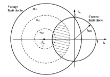
The operating range of a motor is defined by the intersection of two circles, one for the voltage limit and one for the current limit. For our purposes, it's simpler if we assume that the motor and inverter have the same current limit. It looks like this:
V-I Limits.png

At low speeds, voltage doesn't matter and you can produce any desired torque up to the current limit. This is called the constant-torque range. In terms of vector control, Iq is controlled and Id is kept to zero. Iq is the current aligned with the EMF, the component that produces useful torque. Id produces no torque, but can oppose (or augment) the magnetic flux. So, in this region, the current is kept aligned with EMF,all the current produces useful torque, and we can produce any desired Iq up to Imax. Note that keeping Id zero does require timing advance.

"Base speed" is the limit of the constant-torque range. In terms we're more familiar with, this is the max-power point, or roughly half of the free-wheel speed of the motor. Above this speed, we can no longer produce maximum torque, but the torque*speed product remains constant so this is the constant-power range (see wr_2 in the picture above). If we keep Id zero, the maximum Iq we can generate rapidly reduces until we can no longer produce any useful torque. Instead, we apply a negative Id, which is called field-weakening (because it opposes the permanent magnet flux). By choosing the right value for Id, we can place ourselves at the intersection of the voltage and current circles, which maximizes the possible torque. The required Id gets larger as the speed increases, which causes Iq to decrease to stay within the limit Imax = sqrt(Id^2 + Iq^2). Basically, this is like adding more timing advance. If eventually Id = Imax, then Iq will be zero and we can no longer produce any torque. This is the limit of the constant-power range.

Now comes the important part, which I'll quote directly from the paper: "If the inductance is large enough, the constant power speed range can be infinite." In the picture above, the center of the voltage circle is given by the ratio of the PM flux density to the inductance. If the inductance is large enough, this point will be inside the current limit circle, which means that we will always be able to produce some useful torque even at very high speeds. If the center is outside the current circle, then there will always be a finite speed at which we can no longer make Iq > 0, thus above this point we can't produce any torque.

So, a higher-inductance motor will actually be able to produce torque at a higher speed than a comparable low-inductance motor. I have to admit I actually didn't expect that result, but after reading I understand why and how. I will note that this doesn't say anything about inductance vs. power or inductance vs. power density, so I'll leave that part of the discussion be. The paper also does note that, in general, a low-inductance motor will have a larger CT region and a high-inductance motor will have a larger CP region. The specific application here is to a sinusoidal-EMF motor (PMSM), but the application is similar for a trapezoidal motor and square-wave commutation.
 
Wow so I wonder what the with in reason numbers are..... Like im sure there is a point of dimishing returns.
 
Back
Top