jonescg's NEW electric racebike BUILD thread!

We used a system like that last year , absolutely no problems. This is the improved version. I will upload some pics from the pack later today. The pocket bike battery is also assembled with this system and it is working wonderful since one year!
 
^^^well ok if you say so.... Sorry CHRiS, but to me that looks like some failure waiting to happen sooner rather than later due to what you covered regarding the copper sucking up the heat, i just can't
see the joins being reliable? Am i wrong? ts just my opinion.... thin tabs to 2mm copper joins to the cells will be fine i would worry about the connection to the copper......hrmmmz...i wish i could offer some useful advise buddy...as always wish you well and will follow and hopefully learn something new :)

KiM
 
It's hard to tell how well the tabs are soldered under the copper sheet. You could drill tiny 'lightening holes' in the copper and feed solder through them to the tabs below?

Another idea: keeping the tabs straight up and bolting copper blocks to the side as seen here:

http://www.endless-sphere.com/forums/viewtopic.php?f=9&t=34124

Or, could you solder more tab material to the existing tabs until they are long enough to terminate however you'd like?
 
They are great cells, especially for the energy density and their small format - means I can fit more of them in the body of a bike and have less wasted space. The single biggest problem is the short tabs :x

Kim - I haven't thought out a good means to utilise fibreglass, but one issue is cutting slots thin enough to fit the tabs through. I believe 3 mm is about as small as you can go? How do you think I could make it work? I still have my heart set on screws to terminate them, simply cause it will look a million times better than my duckshit soldering. The main thing is to use the front panel of the battery pack as both a wall and a termination panel. Better use of space, really.

Abraham - good suggestion on soldering longer tabs to them. I might try that yet. I have actually bought a hand punch from RS so I can punch 4 mm holes in each tab when I get that stage, but these lumps of copper will be my first failure test.

What do you reckon? Red to black and wait for the solder to melt?
 
jonescg said:
but one issue is cutting slots thin enough to fit the tabs through.

Dremel with a cut off disk will do a 2mm wide slot no problamo CHRiS... ~40 bucks
for a Dremel knock off at Bunnings, the OZiTO Rotary tool is your best bet comes with flexi shaft
included for that price makes it much easier to do intricate work...

Here's a waterblock i made some years ago CHRiS, the channels i did freehand with
the Dremel and a cut off disk... The block was used to cool the hot side of a peltier
on my PC watercooling setup.

DSCF1211.jpg

KiM
 
TD - not bad, but if there was a way of making it more compact that would be better. I have also been reminded that screwing the terminations together only really works well if the entire clamped bit is metal to metal (i.e. copper plate through tab to brass backing plate). I will come up with a few ideas today hopefully.

Meanwhile - did my soldering stand up to the task?

Currenttesting.jpg


At 186 amps (7.5C) the terminations are stone cold, busy thinking about what they plan on having for breakfast. So even my shitty soldering is enough to take roughly half of what I plan on giving it. I will try to make some decent cables out of 50 mm2 cable, cause my 200 A jumper leads aren't up to the task.
 
jonescg said:
...if there was a way of making it more compact that would be better.
Of course, form-factor is at your discretion.

Merely illustrating using fiberglass bar-stock (or other plastic) as a clamping frame, rather than slots in a fixed plate.

I haven't been reading closely enough to get the dimensions of the cells... with those, I could do a workup to scale.
 
[youtube]A1RY_6gMU_M[/youtube]

I also tested it with both clamps on one side, utilising twice the cross-sectional area. I managed to get a burst of 600 A, which later settled down to 400 A. Again, the soldered terminations didn't roll over in their sleep, while the booster cables are suffering some serious heating :D

Conclusion; even my lousy duckshit soldering can still handle very high currents without failure. It's just a royal pain in the arse to solder the whole pack together. Back to the drawing board for more clamping ideas...
 
more compact...?

clamp1.gif

EDIT: looking at it this evening; I think it would be better to use straight strips on the ends that extend beyond (or above) the rails and join those in parallel , rather than using them bent into hoops as above. The hoops unnecessarily double the thickness between the rails, requiring spacers for the series connections.

Jones-Batt1b4.png
 
It looks good - very neat little animation!

I was wondering though about connecting the next layer of cells in series above this block. You could plausibly flip the cells so you can bolt through?
 
jonescg said:
I was wondering though about connecting the next layer of cells in series above this block. You could plausibly flip the cells so you can bolt through?
If I understand correctly, each string would be 6s?
 

Attachments

  • Jones-6s1-400.png
    Jones-6s1-400.png
    16.9 KB · Views: 5,399
Not quite what I had in mind - if you flip the top half down then yeah, something like that. More drawing board I think. I really want to be able to tighten the tabs down with metal on metal...
 
Chris
Have you given any thought to the Haiyin cells ?? Luke was supposed to receive some samples and test them. Maybe he has done this ??

They are being built into a RACE pack for the Connecticut dude, so, through him, maybe Haiyin would help with some support at a reduced price for those higher?? rated capacity-discharge cells, Maybe ?? They have larger thicker tabs you might be able to work with, easier ??

Getting them drop shipped from China, through Ron's distributor ship, might be possible ??

Just looking at this from another angle :)
 
Unless Haiyin are feeling really generous, that would more than double the cost of his pack ! :shock:
I would be much better to go back to "plan A" with the 20ahr, A123's..which people are picking up for $40 currently !
... and would probably have a much longer working life than the Haiyin cells !
 
Yeah, have to agree. I have options on the table if it all gets too hard, but a 120 cell stack of A123 pouches is a good option. It will mean a lighter pack with only 3/4s the capacity, but a highly reliable, trouble-free pack. Still not convinced that the Turnigy's are spent yet, but we'll see.

On the subject of a stack of Turnigys, would the weight of 8 kg worth of cell on top of the lowest cells present an issue? Danny Ripperton believes that you need to leave a 1 mm gap between all of the cells to prevent overheating and he thinks that compression of any kind is bad news. Is there any basis to this? I think it's only an issue when you over-charge or over-discharge, but if you keep maximum C rate at half of their continuous rating, this shouldn't be an issue?
 
Chris, i have started a discussion on similar lines ( ref "C" rate and cell life issues) in Batt tech http://endless-sphere.com/forums/viewtopic.php?f=14&t=34239
Temperature is a factor for consideration , you need some to get the best from the pack, but too much can possibly hurt cell life, so i can see where spacing the cells could be beneficial if you are pulling high current for extended periods.
but.. what is "high current" and what time factors are important ??? :?
And how would you support separated pouches for a pack subject to race vibrations & shocks ?
 
I know - a big stack with no gaps is energy dense and easy :) Danny has his held in place 1mm apart, and it's a right royal PITA to assemble and disassemble. I still think he has two big problems - he skimped on the terminations for weight reasons, and any heat generated in the cell can't be sunk outside the cell. Also, he is running his cells close to their maximum rating, which is not a good place to be.

As for discharge rates, if I have 40C Turnigys, which are considered a "continuous" figure, a maximum current of 400 A at 400 V (160 kW) is still only draining the cells at less than 20C. And this is only part of the time. I did run my 3P pack at 36 A for 25 mins, (2.5C) and they were warm to touch. I doubt they were hotter than 35'C, but strangely, after running my 5P2S pack at 200-500 A for a total of maybe 2 minutes, they were still ice cold.

I don't think I will be abusing them, even with 'harsh' treatment. Overspec and underuse - a good way to ensure things last a bit longer and not catch fire.
 
Chris,

I have been watching with interest all your plans around your new pack.
Honestly I think if you are going to be running at 1/2 continuous C as your peak then you won't need air gap or any other cooling. I agree that Danny had issues due to small connectors and running the pack at over continuous C. I think that applying light compression to foil cells should be done just like ALL the manufacturers recommend.

I do think the pack has to allow you to insert/remove parallel groups and then individual cells easily. This allows for simpler checking and replacement if required.Turnigy Hardcase pack
I have been looking at the Turnigy Hardcase packs and thinking about a slide in arrangement for them. I might try and draw up what I am thinking about...
 
Regarding building the cells into packs, I had some thoughts here:
http://www.endless-sphere.com/forums/viewtopic.php?p=497517#p497517
that may not apply to your cells, but might be helpful:

*****************************************


After some thought and various pics around the web and ES of cells and terminations, I think that what I seem to recall was the EIG NMC pouches appear to have the best easily-stackable method. I am not totally sure how they work, and I cannot now find any of the pictures I have seen over the last months that were labelled as of those types, just one that I think might be, so I might be mixing up different manufacturer's methods into a mishmash that might nto actually work. :? Lots of the pics were very low resolution so I am not certain of details, just guessing based on stuff I do know about various ways things are commonly put together.

The only person on here that I'm sure could verify this is Jay64, as he actually has some of these cells, presumably including the hardware I think I am remembering.


Basically, I think there are short brass (?) plates welded by some method to the actual cell tabs. These plates are 90-degree bends, with two holes in the part perpendicular to the cell itself. I can't find the pic of the cells that looked like this now, but I thougth it was on ES in one of the A123 threads. Might be a "lost image" after the problems this summer. :(


The cells lay flat in trays (plastic?) with the bent plates down over a set of what must be molded-in threaded "nutserts" in the end of the tray. (couldn't see the actual trays or nutserts in the pics, but it's the only way I can imagine it workable).

There are alignment holes in all the trays so they can be easily stacked and bolted together thru the corners or edges (not totally sure about this, but it would make sense).

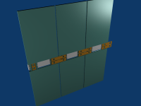
Once your series cells are all stacked up, angled bussbars are bolted thru the plates on the tabs into the trays. Angled so that they connect the + of one cell to the - of the next without flip-flopping every other cell. I'm not sure how easy this would be to do without potential shorts on the cells, but I saved an enlarged version of part of a pic of a pack that shows what I think is this method:
file.php


Anyway, if you don't have room for a wide stack of cells you could bolt a plate across several stacks of these things and tthen bolt cables or busbars between each stack for series connections.

Paralleling them is easy, as you just use busbars across all the negs and other busbars across all the positives, and can even just use extra-wide ones to bolt across sets of them to create extra pack stiffness.

Because the trays are doing all the supporting, there should be no stress on the tabs at all, unlike some of the other methods I've seen proposed that would require a box be built around the pouches that supports them as a group, that is then bolted to all the cell interconnect hardware.

The only real problem I see with the whole idea is that I can only imagine injection-molding as the way to make the trays including nutserts/etc., and that is probably going to be pretty expensive per-tray unless someone does it as a venture to sell them to all those people with the A123 pouches.

Hopefully this all makes sense without a drawing, but I can try to sketch one up if it doesn't.
 
Regarding battery heat. How about finding a way to discharging one of your loose cells at 10C,20C, and monitor the temp. This should tell you if you need to do anything special. If they are still not getting hot then ditch the idea of spacing the cells apart.
 
Ok I can't draw for crap....

Using these batteries....
NC5000.1S2P.5-2(1).jpg


Imagine (if you will) a channel [ ] with a solid back that the battery slides into...
and you have say 4 of these channels stacked on top of each other each with a battery in it.
[____]
[____]
[____]
[____]

At the front you have 90 degree connectors from the batteries into a bus bar up the full height of the stacked batteries.
[_|_|_]
[_|_|_]
[_|_|_]
[_|_|_]

These bus bars would then be 3.7 volt and 20ah with a 50C rating continuous (1000amps).

Total height 92mm (19mm battery and then 4mm spacing for the channels), depth 100mm (93mm battery + bus bar etc) and 53mm wide (47mm + channel width). Approx 640g (148gm per batt + mounting gear) so 115Wh/KG. (all made up numbers). Compared to a 3.3V A123 prismatic of about 500g so 132Wh/KG (bare cell).

Price about $80AUD for the batteries and shipping. Stack as many as you need....
 
I think I get what you are saying, Tony. Still convinced I can avoid busbar and spaghetti junction wiring by going with bare cells - just need to nail it somehow. I think I am close.

For any interested parties - the TTXGP rules have been updated. Maximum permitted system voltage has been increased to 700 V :shock:
 
:shock: At what point do they think its dangerous.
 
Back
Top