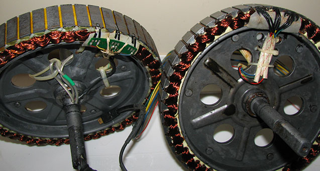
Motor Hall Sensor and Harness Replacement

so what hall sensors can you actually use? the ones on the ebike sites dont have the model number. they can probably be had for cheap on digikey. anyone know what ones are acceptable? i would imagine they have to be digital and have to have a certain sensitivity.
 
motors use digital latching sensors with open collector outputs. they latch when the "S" is close enough. this turns on the open collector transistor. it will stay on until the "N" pole passes by close enough to reset the latch. that is true for sensors with the numbered side facing you. if it is flipped over reverse the "s" and "n" in the explanation.

the selection is non-critical. but the Honeywell SS40A series looks to be the most common. it is the ones used by Crystalyte, BMC/Puma and Cyclone as factory stock at least.

i have used them in several motor rebuilds and i have yet to find a motor where they did not work.

rick
 
digikey has them for about a buck each part #480-1998-ND

rick
 
Sorry to dig up such an old thread :oops:

My MAC has developed a fault where it just won't run properly anymore.
Trying to run the motor as a whole wheel just produces a kind of whining sound. It looks like it's trying to go but cuts out completely after about 3 seconds.
I've taken the motor unit out of the wheel and removed the sprag gear assembly.
Holding the axle firm and slowly twisting the throttle, it spins for up to 3 seconds, then stops.
Only releasing the throttle and twisting again brings it back to life, but still only for a max of about 3 seconds.

I tried using Knuckles hall testing procedure with a multi-meter and got the following:

Negative and blue showed nothing, even whilst turning the wheel as in the video
Negative and green showed just over 5 volts and didn't change whilst turning wheel by hand
Negative and yellow showed just over 5 volts and didn't change whilst turning wheel by hand

Would this test still work for a geared motor and does it look like at least one hall sensor is defective?
 
alfantastic said:
Sorry to dig up such an old thread :oops:

My MAC has developed a fault where it just won't run properly anymore.
Trying to run the motor as a whole wheel just produces a kind of whining sound. It looks like it's trying to go but cuts out completely after about 3 seconds.
I've taken the motor unit out of the wheel and removed the sprag gear assembly.
Holding the axle firm and slowly twisting the throttle, it spins for up to 3 seconds, then stops.
Only releasing the throttle and twisting again brings it back to life, but still only for a max of about 3 seconds.

I tried using Knuckles hall testing procedure with a multi-meter and got the following:

Negative and blue showed nothing, even whilst turning the wheel as in the video
Negative and green showed just over 5 volts and didn't change whilst turning wheel by hand
Negative and yellow showed just over 5 volts and didn't change whilst turning wheel by hand

Would this test still work for a geared motor and does it look like at least one hall sensor is defective?

Could someone shed some light on whether this could be a hall sensor problem, please.
I'm ready to go ahead, order the parts and carry out the replacement, but would rather not if it's unnecessary.
When my free-wheel side cover broke, I limped home for 2 miles on about quarter throttle.
It conked out around 500 metres from the house.
Wonder if this could have blown the sensors or something else?
 
I am curious: Are you certain it's the motor having an issue and not the controller? I only say that cos of your statement about the "whine" and giving out after a few seconds. Having just gone through my pair of motors - and replacing the Halls on one... I am curious about the perceived noise. Is it a high-pitched whine with the motor static (not turning) or when it spins (if it spins)?

~KF
 
It's weird. With the wheel as a whole it doesn't really want to turn, but on occasion will spin slightly. It makes a fair amount of screeching noise whilst doing so.
I originally thought it was the sprag assembly. So replaced that with a new one.
When I have just the bare motor in my hand, it spins ok for up to three seconds, then cuts out. It makes a small perceivable screeching noise, but not as bad as when it's loaded up.
It appears to struggle when applying any sort of load, as in the sprag gearing and wheel.
Whether I turn the throttle a little or fully, it will only run for up to 3 seconds.
I had read somewhere that the controller will automatically shut down if it receives abnormal readings from the hall sensors.
Plus Knuckle's hall sensor test suggests they may be at fault.
My brain hurts :?
 
Re-reading your post, I’ll need to defer to MAC people cos I don’t have that sort of motor.

However - on a lark, have you changed the phase or signal wires recently, re-ordered them in any way? :)

In a wild guess, KF
 
I made my own test rig and established that just one of the hall sensors in the motor has failed. The green lead.
The rig tests the motor without the controller connected, so I can establish that it isn't a faulty controller giving me false test readings.

I want to check to see if the controller hall connector side of things is functioning ok.

Without the hub motor (hall or phase) connected to the controller and controller powered up.
The black and red on the connector show 4.51v on the multimeter.
Black and blue - 5v
Black and yellow - 5v
Black and green - 5v

Now I'm guessing (please correct me if I'm wrong) that when a hall in the motor switches on, it grounds that 5v in the corresponding lead in the controller.
This tells the controller the logic to fire the phase wires at the correct time?
Big question is, does a 5 volt reading on each of those controller pins suggest that the controller is actually ok?

I'm sure someone will decode what I'm trying to explain :roll:
 
IIRC the sensors are powered by the 5v coming from the controllers 5v bus, whenever the correct polarity of magnet gets close, the output goes high (whatever the input voltage is) , and when the opposite polarity magnet is near, the output goes to 0v.
 
Farfle said:
IIRC the sensors are powered by the 5v coming from the controllers 5v bus, whenever the correct polarity of magnet gets close, the output goes high (whatever the input voltage is) , and when the opposite polarity magnet is near, the output goes to 0v.
I understand that the contoller supplies the 5v to the sensors and they use that voltage in conjuction with a magnetic field to switch high or low. In my case this would be 5v and 0v. What I need explaining is how the hall sensor output is related to the controller, so the controller knows that a hall is either high or low. Does a high state effectively act as a switch, which in turn grounds the 5v at the controller end. I don't think I've explained that very well. Maybe someone could provide a link to a technical site to help me understand.
 
Look up the spec sheet on a hall (like the Honeywell SS41 series) and you'll see exactly how they work.

But basically they are often open-collector outputs, so as they switch, they simply turn on the output that shorts to ground. A pullup resistor (often inside the controller) keeps it at 5V or "off" when not being pulled to ground by the hall.
 
My 9c 2810 has a hall out and replaced them and the same A is out after two hall sensers. How do I check the board or buy a new pcb board with the surface resistors and halls ? Can't see any problems with the traces.
 
Lyen said the old 9c didn't have the board and just wire it up. Do I hook all pos. halls to the pos.sense wire and all neg. to the halls neg. in a bundle. Then hook the ABC or B-Y-G to the right halls. That's it ?
 
Both of my motors are 9C-clones (or 9C rebranded as EBike-Kit); one has the PCB and the other does not; they're both disc FH and RH purchased at the same time - go figure :roll:

You don't need the PCB to wire it up. I replaced the Halls on the RH last month w/o using the board.

P1-1202.01.FR.jpg

FH on the left, RH on the right; different wire colors for A-B-C from the same manufacturer:
FH = Y B G, whilst the RH = B Y G; both are read as A-B-C from left to right.


HE Wire Order:
From Left to Right, regardless of WIRE COLOR, the channels are A-B-C.

When you flip the motor around and look at the Phase wires, regardless of COLOR, it is also from L->R; A-B-C.

How this hooks up to the controller can be different depending on FH or RH, and with different controllers. Don't get locked in on the wire colors except that the HE and Phase use the same color per channel from the stator to the connector. The order at the connector is up to you :)

Best of luck, KF
 
Thanks Kingfish but One question. Hook all pos. halls to red and bundle all neg. then just the A-B-C in order. Yes or No just that answer please.
 
999zip999 said:
Thanks Kingfish but One question. Hook all pos. halls to red and bundle all neg. then just the A-B-C in order. Yes or No just that answer please.
Correct - Yes. PITA, but that's exactly correct. :wink:

Cheers upon your success, KF
 
Help to us thesimple peappol it's hard and hurts the cocuonut for days before and after. I will there fore find the correct color and lenght of wire for your earlier theard. I love people smarter than me . The steps. Thanks Robert
 
I looked and looked at that board till I got part of the traces now this is a simple board so I had a chance. Hours later I found the resistor a 101. So on an old ping bms I found a 101 a little smaller but a 101. And with a weller solder gun 100-140w 8200 I knock off the resistor and melted it on. WOW it worked on the bench with the Lyen tester. Thanks a lot guys.
 
Back
Top