RC mid-drive build from scratch. 80100, HV160, aim = 40mph+

Sellick

10 W
Joined
Oct 18, 2013
Messages
69
Hi everyone, I am a new member to the site and have an exciting and ambitious first project. I put a quick post up in the 'general chat' area explaining it a few months ago, and I have spent that time glued to endless sphere, learning as much as I can! I am studying Mechanical Engineering in the UK, and my dissertation project is to build an ebike. The project isn't very restrictive at all, with my only aim being for it to reach a maximum (not sustained) speed of 40 mph. I am also very lucky because I have full access to the university's workshop, which includes CNC milling machines, lathes, MIG and TIG welders, plasma cutters, and more! Before I started the project I was a keen downhill mountain biker, but had absolutely no knowledge of electrical systems, or ebikes, so I really welcome any suggestions or corrections if I go off-track. So, I thought I would start by listing out the shopping list of parts I am hoping to use:

- 80100 7kw motor (180kv)
- 4 x 6s Zippy Flightmax 5000mah 40C LiPo batteries (to be run in 12s2p, not sure if this will be enough yet?)
- Hobbyking power supply
- Turnigy Accucel 6 charger
- Cell log
- 4 x low voltage alarms
- Castle Creations HV 160
- Magura throttle
- Cycle Analyst
- Neugart PLE gearbox
- 3-speed internally geared rear hub
- Custom jackshaft
- Custom frame
- Swingarm from DH bike (or possibly custom)
- High-end DH bicycle components

I am on a tight budget, so there are some things I would like, but I have had to compromise somewhere (would like an Astro 3220!). Now, I know the components I want to use for powering it, but I'm at the stage where I need to design a frame. I am really unsure whether I should go for a big DH style bike with fox 40 forks, and loads of travel (maybe even make it look more like an mx bike), or take inspiration from the Audi ebike, and go for a smaller, lightweight frame. Either way, I will be using a jackshaft, which will double as the rear wishbone mount (maintaining the correct chain tension). I have SolidWorks CAD so I will start to draw up some designs, and update you with my progress. Any ideas for frame inspiration, comments on the above, or advice would be greatly appreciated!

Thanks very much
 
Hi Sellick,
Some things to consider if you are a tight budget ..
Use halls sensors on your motor ( much better control and starting ability than sensorless ) and then use a much cheaper controller then also no need for a full blown cycle analyst ( just use a cheap watt meter ) . if you are only buying a small 6cell charger (50W) then a 15v ,5A laptop psu will do the job to power it ( about £6 delivered from ebay ). if you have not already got your motor then consider the 8085 motor its not so long and will still be able to push a e-bike @40mph+.
A 3 speed rear hub may not be able to handle the torque from a motor that is producing 3+ kw ( unless you are only going to use the geared rear for pedal power).
 
Hi,

Ww have been working on a similar project for the last few months here in the UK. Our bike consists of:
2 Astro 3220 motors with Torque reduction system
2 Phoenix Ice 2 HV 160 ESC's
Cycle Analyst V3
Magura Throttle
Custom Power supply - bonkers and dangerous!
Bike is custom built using Boardman Full Suspension mountain bike frame, custom built wheels with custom drive train and axles.

One of the main problems we have encountered with this build is the CA V3. When we test the drive system using a servo tester, BEC, throttle we get only marginal power that is jumpy and slightly unpredictable. The problem is when we try to use the CA V3 as the ESC's don't seem to respond to the signal. We can see that the throttle input in put is fine and the programming of the ramp up and down is great and will give us the control we need for this extremely powerful system, however the ESC's won't respond. We don't get a confirmation signal or anything.
It would be great to know of you have any idea on how to solve this?
May be you would like to come and have a look at our build?
 
Psycholist666 said:
Hi,

Ww have been working on a similar project for the last few months here in the UK. Our bike consists of:
2 Astro 3220 motors with Torque reduction system
2 Phoenix Ice 2 HV 160 ESC's
Cycle Analyst V3
Magura Throttle
Custom Power supply - bonkers and dangerous!
Bike is custom built using Boardman Full Suspension mountain bike frame, custom built wheels with custom drive train and axles.

One of the main problems we have encountered with this build is the CA V3. When we test the drive system using a servo tester, BEC, throttle we get only marginal power that is jumpy and slightly unpredictable. The problem is when we try to use the CA V3 as the ESC's don't seem to respond to the signal. We can see that the throttle input in put is fine and the programming of the ramp up and down is great and will give us the control we need for this extremely powerful system, however the ESC's won't respond. We don't get a confirmation signal or anything.
It would be great to know of you have any idea on how to solve this?
May be you would like to come and have a look at our build?


Where abouts are in the UK ??. The input to the ESC's are not a straight forward up and down voltage ramp to make them work, RC ESC's use a PWM input for the throttle, The CA is able to do this but I dont think its by default.

2 Astros on a bicycle would be insane power and very intresting to try and ride :D , it would have to be geared very tall to make it useable :twisted:
 
Very cool idea, current will need to be kept low to get 100-120 RPM cadence at crank from any Astro since they want to spin at 7500 RPM to be efficient (.93%).

If I can be of assistance in design let me know, I do have a few Astro's on Hand, a used 3210 10T 135 kV, a brand new 3210 135 kV and a 3220 6T I believe also brand new, finally I have an HV ICE 120 and HV ICE 160 also brand new.

The 40 mph is doable easily presuming 26" bike you need to sustain 516.92 RPM at the rear wheel which depending on cassette, cluster and chainring is fully possible, an example:

11t Rear Smallest Sprocket, 52t Front Drive Sprocket
That gives you an increase of: 4.7272 : 1

516.92 / 4.7272 = 109.286 RPM Cadence at the crank

Now the tricky part - to get the Astro motors up to 7500 nominal RPM, you will need a reduction of 68.62 :1

Assuming you could BB mount a casing - similar to the Bafang Methods, your best ratio is likely to be no better than the GNG drive or 80 / 14 for 5.71428 : 1, lets say we could achieve that reduction and jackshaft over for a second reduction to the cranks, you would need 12.0085 : 1 reduction between output of the jack shaft and input of freewheeling cranks.

There are solutions, Im sure you will find em. If you do go Astro and mount it in a protective enclosure I might suggest a case clamp to draw heat away for better thermal dissippation.

Regards,
Mike
 
Where abouts are in the UK ??. The input to the ESC's are not a straight forward up and down voltage ramp to make them work, RC ESC's use a PWM input for the throttle, The CA is able to do this but I dont think its by default.

2 Astros on a bicycle would be insane power and very intresting to try and ride :D , it would have to be geared very tall to make it useable :twisted:

Since writing the above post I found how to wire up the CA V3 properly and where to attach the wire for the PWM signal. So now we have full control over the motors. The gearing is a head ache - trying to find components tough enough to take the torque that will be produced. I've witnessed for myself what happens when you a human powered bike changes gear too fast (CRUNCH and lots of bits everywhere).
 
mwkeefer said:
Very cool idea, current will need to be kept low to get 100-120 RPM cadence at crank from any Astro since they want to spin at 7500 RPM to be efficient (.93%).

If I can be of assistance in design let me know, I do have a few Astro's on Hand, a used 3210 10T 135 kV, a brand new 3210 135 kV and a 3220 6T I believe also brand new, finally I have an HV ICE 120 and HV ICE 160 also brand new.

The 40 mph is doable easily presuming 26" bike you need to sustain 516.92 RPM at the rear wheel which depending on cassette, cluster and chainring is fully possible, an example:

11t Rear Smallest Sprocket, 52t Front Drive Sprocket
That gives you an increase of: 4.7272 : 1

516.92 / 4.7272 = 109.286 RPM Cadence at the crank

Now the tricky part - to get the Astro motors up to 7500 nominal RPM, you will need a reduction of 68.62 :1

Assuming you could BB mount a casing - similar to the Bafang Methods, your best ratio is likely to be no better than the GNG drive or 80 / 14 for 5.71428 : 1, lets say we could achieve that reduction and jackshaft over for a second reduction to the cranks, you would need 12.0085 : 1 reduction between output of the jack shaft and input of freewheeling cranks.

There are solutions, Im sure you will find em. If you do go Astro and mount it in a protective enclosure I might suggest a case clamp to draw heat away for better thermal dissippation.

Regards,
Mike

I think with that motor power it is better to spin the cranks at 200rpm plus so you can exert less torque on the fragile crank freewheel and use the larger sprockets in the back. Cuz if you have too much torque the chain and you shift the rear derailleur the wrong moment the chain can come off when you're going up hill at 35mph and your derailleur hanger can break off and get caught in your back wheel and then your wheel locks up and you almost get run over by the car behind you and then you have to walk your bike home (with the back wheel stuck) and get a new wheel and derailleur and derailleur hanger (which can be really hard to find if your bike is 10 years old or so)
 
Thanks for the response! I do already have my motor ghwy, but thanks for the suggestion. I went for the CC controller just because everyone seems to have great success with them, and I do love the cycle analyst. Also, I have read that the nexus hubs are pretty tough, but I do appreciate your experience! Psycholist666, that build sounds incredible! I would love to see it, where are you located? Unfortunately I don't know anything about your problem, but I would say you're certainly in the right place!

Thank you for your input Mike, but as stated, the bike will be using a planetary gearbox for the reduction, and a separate jackshaft (not the crank axle) to submit the power to the rear wheel, so cadence or crank RPM doesn't really come into it at all. Cooling is certainly something I need to consider though. Also fizzit, I'm not using a derailleur.

Any ideas for the ultimate frame design?!!
 
Hi Sellick,

We are based in Oxford, if you want to come over and have a look you are more than welcome. Seeing as you are using the same motor principles as we are please don't hesitate to ask if you need any help with the set up in exchange I sure do need some advice on torque effects on components and could also use someone with easy access to CNC machinery, at the moment we have had most of our custom parts made by a precision engineering company who make parts for various F1 teams around here and the research companies and they are good but as we know we don't always get it right first time so it has been a bit expensive!!!
 
Psycholist, unfortunately every part I make has to be drawn in solidworks and signed off by my supervisor! Quick update, the frame pictured I am just stealing the rear swingarm/shock linkages from!


Ordered all my parts from America, just waiting on shipping! Also just finalising frame design. I was going to go for a large frame, triple clamp forks, and a chunky rear shock, but I'm now thinking of keeping it short, light, and compact. The weight savings from the smaller forks/shock will be considerable! So compact and lightweight are key. Taking massive inspiration from the audi ebike, just would really like the motor/gearbox to be a bit slimmer! Any input would be great. I'm also hoping the 4 batteries will be enough, but we will soon see. Hoping to have the frame finished end of Feb, along with all other components ready for the build!
 
yawstick said:
gwhy! said:
if you have not already got your motor then consider the 8085 motor its not so long and will still be able to push a e-bike @40mph+.

Where can you get the 8085 motor.... I asked that in another thread and no one replied.


I get mine from http://www.giantshark.co.UK
 
I am actually considering going down to an 8085 motor just because I wanted to keep a standard width bottom bracket and don't want the motor to be too wide. It all depends how wide my gearbox is going to be. Gwhy, any more advice?! Anything you can tell me about frame design?
 
Sellick said:
I am actually considering going down to an 8085 motor just because I wanted to keep a standard width bottom bracket and don't want the motor to be too wide. It all depends how wide my gearbox is going to be. Gwhy, any more advice?! Anything you can tell me about frame design?

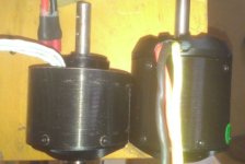
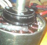
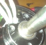
I cant really give any advice about frame design or gearing as I have never set one of these motors up to drive through the cranks ( but I have a few ideas of maybe a better way of doing it ,if making a frame from the ground up ) . I would remove the skirt bearing from the motor and also the end cap of the motor then cut the outer can down by about 7mm , this way you can reduce the width of the motor by a further 5-7mm ( ask if you want to see pictures ) and it allows a little more air flow through the motor to help keep things a little cooler. you could also do this with the 80100 and this 5-7mm reduction in width may be enough for your needs.

edit: just re-read you OP so are not planning to peddle along with the motor power ?, as You say you are not planning to drive through the cranks.
 
wow that's great, I didn't think I could get away with that much reduction in width! I'm planning on using the swing arm pivot/mount as a jackshaft, very much like the motoped. I.e. this is a spinning shaft, the motor drives it, the pedals drive it, and it drives the rear wheel. This means the chain length won't change as the rear suspension is displaced. I will still be having cranks/pedals, they just won't be used in conjunction with the motor. The other thing I wanted to ask you.. I've seen a lot of people use a support bearing for the motor shaft (often the other side of the chain line to the motor), would you recommend this? It does seem like a lot of force is exerted on that little shaft. Thanks again!
 
Sellick said:
wow that's great, I didn't think I could get away with that much reduction in width! I'm planning on using the swing arm pivot/mount as a jackshaft, very much like the motoped. I.e. this is a spinning shaft, the motor drives it, the pedals drive it, and it drives the rear wheel. This means the chain length won't change as the rear suspension is displaced. I will still be having cranks/pedals, they just won't be used in conjunction with the motor. The other thing I wanted to ask you.. I've seen a lot of people use a support bearing for the motor shaft (often the other side of the chain line to the motor), would you recommend this? It does seem like a lot of force is exerted on that little shaft. Thanks again!

The peds driving a jackshaft ( pivot point ) that is also driven by the motor is the way I would go also , This way you are not restricted to using standard bike chain to the rear wheel so you can use a much larger rear sprocket ( more reduction ) and if you are using a geared rear hub it will still give you a few on the fly gear options and or front chainring gear options .. a support bearing on the out side of the chain is not necessary as long as the out put shaft dont stick out to far from the inner bearing, the standard bearings that are in these motors are not really up to the job of the amount of side forces for e-bike use so ideally you will need to incorporate a additional bearing somewhere in the system and where it will be best to put it will depend on how its designed, sometimes this can be on the motor side of the OP sprocket but if you can make space then the outside of the sprocket will do, upto now I have had no problems with using just 1 28od x8 x12id sealed bearing for this but you may get away with just adding another 1 or 2 of the smaller ( motor size ) bearings.
 
That's excellent, thank you. I will try to squeeze a support bearing in there somewhere! If you have those pictures of the 7mm reduction that would be fantastic too! Thanks very much
 
Sellick said:
That's excellent, thank you. I will try to squeeze a support bearing in there somewhere! If you have those pictures of the 7mm reduction that would be fantastic too! Thanks very much

I will take some pics and post them here over the next couple of days...

Another good reason for not driving the cranks with the motor is the comon problem when using a freewheel on the BB, you could get away with using a oneway bearing on the jackshaft instead, so you will not have to have the motor pulling on it all the time so will make the system more reliable.
 
a picture of one of my old 8085 cutdown ( reduces length by around 7mm )

motor1.jpgmotor2.jpgmotor3.jpg

you could get rid of about another 5mm if you turn down the mounting face of the motor ( there are 2 bearings on this end of the motors, so the second bearing can fit into the actual mounting plate that the motor fits to ).
 
gwhy! said:
Hi Sellick,
Some things to consider if you are a tight budget ..
Use halls sensors on your motor ( much better control and starting ability than sensorless ) and then use a much cheaper controller then also no need for a full blown cycle analyst ( just use a cheap watt meter ) . if you are only buying a small 6cell charger (50W) then a 15v ,5A laptop psu will do the job to power it ( about £6 delivered from ebay ). if you have not already got your motor then consider the 8085 motor its not so long and will still be able to push a e-bike @40mph+.
A 3 speed rear hub may not be able to handle the torque from a motor that is producing 3+ kw ( unless you are only going to use the geared rear for pedal power).

sorry to pollute this thread but......what kind of sensored e-bike controller you could suggest that can handle 80-10 amps at 12s lipos and that is much cheaper (or simply cheaper) than an HV160? I would like to have clear info about this!!!

I ask this because I drive My Astro sensorless with the HV, already tried it with hall and with optical Burtie´s encoder, but just couldn´t find a controller that can handle sensored, these currents, at cheap price than a Castle.

Since Castle sell a lot of units to a lot of dealers around the world, is not uncommon to find some of the older model (ICE or ICE2) and sometimes even the new ones (as the EDGE) for 30% or even more discounted prices compared to the List one....

Thanks
 
I use moddified 12fet controllers with 3077 fets, but to get the best out of them use them upto 100A+ then you need to get the gearing/load right and find the optimum setting for the phase current limit for the motor your driving.

cellman sells a 12fet modded controller for around $98 or put one together your self for around $80
 
gwhy! said:
a picture of one of my old 8085 cutdown ( reduces length by around 7mm )
you could get rid of about another 5mm if you turn down the mounting face of the motor ( there are 2 bearings on this end of the motors, so the second bearing can fit into the actual mounting plate that the motor fits to ).
Those are some beefy windings in your motor... Has it been rewound?
If so what kind of current are you pushing through it?
 
gwhy! said:
I use moddified 12fet controllers with 3077 fets, but to get the best out of them use them upto 100A+ then you need to get the gearing/load right and find the optimum setting for the phase current limit for the motor your driving.

cellman sells a 12fet modded controller for around $98 or put one together your self for around $80
Ok thanks a lot for this info abut the price, thougt that 12fets was not sufficient, and anyway couldnt find it at the price you mentioned.
Thanks again.
 
panurge said:
gwhy! said:
I use moddified 12fet controllers with 3077 fets, but to get the best out of them use them upto 100A+ then you need to get the gearing/load right and find the optimum setting for the phase current limit for the motor your driving.

cellman sells a 12fet modded controller for around $98 or put one together your self for around $80
Ok thanks a lot for this info abut the price, thougt that 12fets was not sufficient, and anyway couldnt find it at the price you mentioned.
Thanks again.

http://em3ev.com/store/index.php?route=product/product&path=38&product_id=81 $92.00

12fets is ok but like i said there is no room for error with gearing and load and you also need a fair bit of patience to workout the optimum phase current settings.
 
yawstick said:
gwhy! said:
a picture of one of my old 8085 cutdown ( reduces length by around 7mm )
you could get rid of about another 5mm if you turn down the mounting face of the motor ( there are 2 bearings on this end of the motors, so the second bearing can fit into the actual mounting plate that the motor fits to ).
Those are some beefy windings in your motor... Has it been rewound?
If so what kind of current are you pushing through it?

yes its been rewound , on A good day anything upto 7kw
 
Back
Top