RC mid-drive build from scratch. 80100, HV160, aim = 40mph+

I have just specified an amazing planetary gearbox for this :) much better than the Neugart PLE's, and more compact! The reduction ratio is 10:1. The motor will drive this with a small reduction between the two (i.e. slightly smaller sprocket on the motor) to give my overall reduction. The gearbox then drives the jackshaft and the jackshaft drives the rear wheel, both at a 1:1 ratio due to size constraints. I am unsure on whether to rewind my motor. I'm awful with the electrical stuff, and I'm struggling to understand whether a higher kv will put more or less strain on the controller (although I obviously understand that thicker wire has the potential to carry more current?). I haven't seen anyone use an 80100 with 180kv; everyone seems to go with the 130kv or a rewind (understandable for the lower rpm).

I think the weakest components in my build are the controller and the rear hub. Hopefully I will protect the controller with the capacitors and other mechanical systems.

Gwhy! thank you so much for those pictures! That's a huge reduction in length, exactly what I need! That makes perfect sense about moving the second bearing to the mount too. I see you lose the little black screws on one end of the can, what is their function? I haven't had time to dissemble the motor yet. Thanks so much again for that!
 
Also Gwhy!, do you think a 12S2P pack will be enough? I have four zippy 40C 6S 5000mAh batteries. I guess that won't give me a great range!
 
The little black screws hold the skirt bearing, I remove the skirt bearing..
Range is very dependent on many things , but I normally go by 1 mile = 1Ah ( round trip ) so 10Ah @48v will be a round trip "on road" of 10miles ( un-assisted ) at a top speed of around 30mph .
 
Sellick said:
I'm awful with the electrical stuff, and I'm struggling to understand whether a higher kv will put more or less strain on the controller

More winds = more resistance+ more inductance = less stress on the controller for the same voltage.

Delta wind= faster, more likely to get different resistance + inductance on the 3 phases = likely more loss+controller stress
->more explanation here: http://endless-sphere.com/forums/viewtopic.php?f=30&t=45326#p660952

my proposal: Get a 6T or 8T and solder it to WYE + fix the windings with epoxy. A 6T in WYE has 105KV, which might suit your needs best for 48V. An 8T has ~75KV in WYE (mine had 80KV), which is fine with 72V. Tested it with sensorless Greentime controllers, which works good. It may also work with cellmans 12fet sensorless controllers. Cellmans controllers have better acceleration/ faster throttle response, but suffer more from low inductance. Still, i'd give it a try, in WYE termination expacially the 80-85 may not be too hard for this controller. As gwhy mentioned, be careful with the phase current settings if you really go 100amps.

you'll find more info about this topic in our wiki http://endless-sphere.com/w/index.php?title=RC_Type&action=submit#termination
 
Ah ok, that makes perfect sense too. I believe the skirt bearing has quite a lot of friction too? So would be good to remove it, especially if it aids cooling. I would like to add a small fan to the motor because it will be quite enclosed, but I'm not sure if I will have room. I think the range will be perfect for my needs.

Crossbreak, thanks very much for the input. Just to clear it up, I am using an 80100 motor with a Castle HV160 RC sensorless controller. I'm using this because of the compact size. I believe the 180kv motor comes terminated in delta, with 6T? If I was to re-terminate the stock windings in Wye, this would run 1.73 times slower, and put less stress on the controller? Is that possible? Or would you really recommend rewinding the entire thing (I would rather not due to lack of time and experience!)? It does have a few loose winds in the stock winding which I'm not keen on. Are you saying that with my stock windings terminated in Wye, I will have a 105kv motor with the 80100?

Thanks again
 
Sorry, I've just realised 180 / 1.73 = 104. Guessing that is how you get the figure of 105kv? So there are no downsides to re-terminating in Wye?
 
Hi Sellick

Nice project.....
I would love to get infos about the more compact and lite planetary box than a PLE80.
If this exist, than could be awesome...even a 0.5Kg lighter unit...
Anyway using a Planetary reduction, you need to be careful with the Max sustainable torque it can handle....max out mean the torque after the total reduction before the
output shaft, so it include the reduction ratio of the gearbox+what you would add with sprockets between motor and its input shaft.
If something goes wrong with a belt primary reduction it should be not nice but you could fix it for cheap probably, if something goes wrong with such a $$geabox.....mhh.

So, As it seems you already want to rewind a motor, it's a good Idea to make also calcs of the kt and the max expected torque the motor can sustain to match it better with the max sust Output of your gearbox of choice...
I'm sure you already know this....but is a crucial point/limit for planetarys on our applications....
 
Hi panurge. I think this gearbox might only actually be better because I wanted a 10:1 ratio. The neugart had no where near enough output torque capability at that ratio, but it might for lower ratios. It's a single stage 10:1 reduction with a maximum output torque (peak) of 140Nm iirc. I'm just waiting for it to turn up, and will post more info on it when it does! I was basing my torque calculations for the motor on:

Torque (Nm) = (Power (watts) x 9.554) / rpm

= (6500 x 9.554) / 6912

= 8.98 Nm

I based my rpm figure on 80% of the kv rating (180) x volts (48). With a direct drive to the gearbox, and 10:1 ratio this gives an output torque of 89.8Nm, giving me 50Nm to play with when changing the gear ratio between the motor and gearbox input.

Is this correct?

However, if I re-terminate my motor in Wye, my rpm would theoretically reduce to approximately 4000 rpm, which equates to about 15.5Nm, which would mean I would have to lower the gear ratio between the motor and box to stay within specifications!
 
the motor can't output more torque if you rewind or reterminate it. Just the KV and KT will change. Maybe you get a better copper fill factor if you rewind it, then you can really put in more power (and get out). 104KV or 105 KV? It's the same, the "180KV" is just a guess of the seller, it does not tell you exactly what you really get in the end. I would say this guess is +/ 3% at least.

The HV ESC may burn if you are not careful. I would at least use a Cycle Analyst to limit the amps. What I can say is that the Castle has a lot slower acceleration than the Infineon Controllers, which is an issue if you use a freewheel. Panurge gave me one so I could compare.

Anyway the Castle has no competitors with its package/power
 
Start Figuring out your torque/power needs. (use SpreadSheets, theory and real world datas of similar builds when available)
than Compare them to what the limiting items on the "chain" are, so the ESC at first, than probably the gearbox, and lastly batteries and motor, if well wounded and in a cool environment).

The max power I saw from the CA-LRC on a bike with a Dlux Esc and an 80-100, has been around 3Kw in the asphalt and the motor (rewound at around 100kv in delta) was really hot. than the Esc popped.

With the astro/hv160 setup and a 100Kg total weight I saw 5kw, sometimes, with a 160A CA current limit or with the servo/bec throttle interface (castle log), and extreme load conditions.
I use a mechanical torque limiter, though...so my max power is often seen at moderate to high speeds (top is 50Kph), that's what you would like to see, to take care of the HV ESC.

You cant get more power from a motor if not by better quality windings quality as per crossbreak advice.
You may only works with the kv/kt. My advice was about the max sust. torque, first, but with this TopSecret gearbox you should be fine with 1:1 imput. At just 1.5:1 you are yet not so far from the 140Nm, though...(assuming the 9Nm you calc. is a realistic rate that you may have safely delivered at the motor output)

Cheers
 
gwhy! said:
The little black screws hold the skirt bearing, I remove the skirt bearing..
Range is very dependent on many things , but I normally go by 1 mile = 1Ah ( round trip ) so 10Ah @48v will be a round trip "on road" of 10miles ( un-assisted ) at a top speed of around 30mph .
This site is a such a great resource.... I'm still pretty much a noobie here and still trying to absorb a lot of good information. The 1Ah/mile is a pretty handy bit of information. I have quite seen quite a few references to skirt bearings but what I imagined they were was not even close.... I've not seen a motor with them. From what you said there I suppose they are under the skirt end of an outrunner type motor... are they as large as the skirt itself or close too it? If so I could see where those would be problematic.

I did read most of your "its an emotorcycle now" thread... great stuff.... I'm pretty much a recumbent trike guy but got me to thinking. I have a old yamaha TT 225 dirt bike with a broken transmission that I'm looking at in a whole new way now. :mrgreen:
 
I understand that I can't get more power out of the motor from rewinding/retermintating it, however, if it's producing 6500 watts at 2000rpm less, the torque is surely going to be higher? It's like changing the gear ratio? Sure if you geared it back up so that the output of the gearbox had the same speed, it wouldn't produce any more torque, but the output of the motor is?

Can anyone tell me if the formula above for torque is correct, and also where peak torque might be in relation to rpm?

Thanks again!
 
Yes, your formula is correct. Maximum torque is at 0rpm. Peak power out (theoretically) is at half of the no load speed, at which point the efficiency will be about 50%.

For a given voltage, you can change from a high speed motor to a low speed motor by changing from a delta to a wye connection (or rewinding with more turns) but there's no way to get a "high torque" motor by changing the configuration.
 
Thanks Miles. I understand that, but using the formula, surely if it's producing the same amount of power/torque, but lower rpm's, the gearbox will see more torque? Also, is there any way that I can estimate a power/torque graph? This is my dissertation project, so any technical info/graphs would be perfect!
 
panurge said:
(assuming the 9Nm you calc. is a realistic rate that you may have safely delivered at the motor output)
Cheers
Would say "the motor shaft" sorry, and I mean that a part of the "chain" before the shaft (Most likely ESC - windings/phases/magnets) could be not so safe, before a 9Nm rate is delivered to it :evil:
For the graph, if of any help you could read this page on my old thread where Miles introduced me with some illuminant posts to a week of motor theory reads and a substantial increase of my knowledge... :mrgreen: It is concerning the Astro but you may find some infos useful, Drivecalc and spreadsheets ecc. http://endless-sphere.com/forums/viewtopic.php?f=28&t=25101&start=25#p408609

Cheers
 
Sellick said:
Thanks Miles. I understand that, but using the formula, surely if it's producing the same amount of power/torque, but lower rpm's, the gearbox will see more torque? Also, is there any way that I can estimate a power/torque graph? This is my dissertation project, so any technical info/graphs would be perfect!
A motor will generate as much torque as it requires to balance the load. You can get more torque for the same current but if you rewind or re-terminate to achieve this you will increase the resistance of the motor. The amount of heat generated for a given torque stays the same, no matter how it's wound or how its terminated (assuming equivalent copper fill).
 
Ok, thank you very much everyone for the input! I have been doing a lot of reading! There is so much info around for the Astro motors, presumably because astro are so good at publishing it, and Turnigy didn't seem to give out anything much!

I have the first week in February off and I really want to build the bike then so I'm just trying to order the remaining parts. These consist of a torque limiting slipper clutch, and a kill switch for safety. I know these have been done quite a few times on here, but can't seem to find much info on actual clutches used? I don't know what the torque rating needs to be, since my figures seem to be a very rough estimate! And also, any ideas on a handlebar mounted kill switch, where to wire it etc. would be fantastic! Thanks again!
 
I would avoid any switch, but anyway not at the handlebar. You could consider a relais, but this add another step of complexity and more potential fail points....
A kill switch is a potential fail point most likely than a safer device, for most people, if you ask it here on ES...Personally I only use a reasonably large fuse to protect my batteries from disaster events on the esc side.
The best kill switch is to have dielectrics gloves and the main leads at hands to be pulled :D
Nautics, CarAudio and Elctric automotive is where they use big an potentially good switches for high currents....the only other device I use is a soft Cap charger resistance as antispark device.
 
I read that people don't use them because cutting the battery suddenly can kill the ESC? But I'm also sure I remember seeing a simple method that would work. I just want it for safety more than anything really! (eg. if the throttle stuck open). Also, the spark eliminator - is it worth it? Will there be a big spark every time I connect the batteries? Thanks again!!
 
I use a kill switch but not for the power, I use a lanyard kill pull on the bars that pulls the throttle down to ground or have it tied into the e-brake. Its a magnetic Lanyard and it connected to my wrist so when ever I get off the bike the bike becomes disabled which has saved quite a few mishaps when people what to look at my bikes and decide that they want to twist the throttle. Spark eliminator is well worth the effort as it helps keep the main contact/plug from getting pitted which will increase the resistance of the plug due to the spark. You dont need a big heavy duty switch to do this there are less costly and more compact methods..
 
I've been looking into this a lot! I've seen a few systems that use a spark eliminator and on/off/kill switch together. These seem pretty cool. I've also read that the castle controllers sometimes don't like it because they think there are less cells available in the battery, but that a 1 ohm 5 watt resistor would be suitable. Any other ideas for a kill switch would be great. Where is this wired in? Is there a way that I can put a switch on the throttle wires to just kill the throttle?! I would rather kill power to the ESC I think? Thanks again for the input Gwhy and everyone else!!
 
I use a 180 ohm5w resistor, since I had them on my audio spares inventory and works fine, with 15-20Ah 12s 3 secs are more than enough to avoid sparks. the Esc arms very quick and you can see the voltage rising into the CA lcd....

I use the resistor in parallel with one of the main plug coming from the esc, so it is always on-board. it has an end soldered to the +plug (esc side) and the other filament free. So, first, you simply touch with the +battery connector, the free wire, and than after a pair of secs, finally plug-in the main connector (esc side).....at this point the resistor is outlined but with the free end exposed, that's not a big problem, and you may even cover it in lot of ways.

My approach (seen somewhere here on ES, sorry but I cannot find the original thread actually) is trivial but smart, lightweight and cheap. Could be obviously refined maintaining the same smart concept; it works great with bullet connectors.

As throttle kill switch, for temporary parking purposes, I use to enter the CA setup. This kills the signal to the ESC. The downside is that The Phoenix feel it like a signal loss when you exit the CA setup, but this does not affect the control in any way.
Due to this CA option (a must option for me actually, but definitively not an emergency kill, having to hold the CA button) I've not experimented any dedicated throttle kill switch as Gwhy did, but it sounds pretty cool... :!:, I would go this way, eventually.
 
This is a standard magnetic lanyard
magnetic kill.JPG

, when the magnet is off the contacts are closed , just connect to the e-brake on a e-bike controller, its a bit more tricky to use this lanyard to pull down the throttle signal unless you play around with a resistor values . Its easy to make your own magnetic lanyard using a miniature micro switch , and you can configure this to go open so you just fit it in line with the signal wire of the throttle.

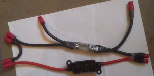
Just for info this is what I use as a spark elimiator/fuse and main battery on/off plug.
6mm lead fuse and anti spark link _2.jpg
 
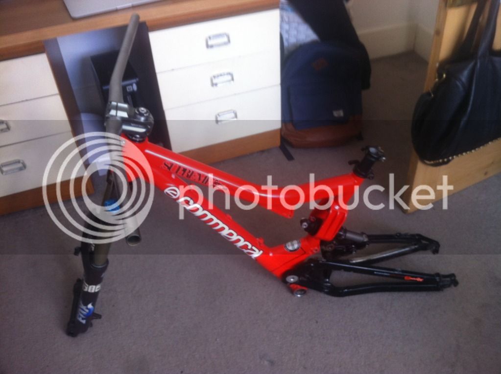
Thanks very much for the help again guys! Just a very quick update, but I've purchased my forks and a few other bike parts. I'm eagerly awaiting delivery of parts from America tomorrow! That's my CA, gearbox, clutch, controller, rear hub, throttle and a few other bits and pieces!


Back
Top