RC mid-drive build from scratch. 80100, HV160, aim = 40mph+

I'm jealous that you get to build an ebike for class credit, that is truly awesome!

I see you are looking for frame advise and haven't really gotten much input, so I will point you to this thread on pinkbike that is sprinkled with great information between the Bullshit DH teenager's posts:

http://www.pinkbike.com/forum/listcomments/?threadid=39840&pagenum=115#commentid1716164


There was some fellows from California that built an ebike as part of thier engineering degree, they really did a stellar job with carbon fiber, they cheated and used a hubmotor though. :roll: .

Can you post up some design sketches that you have, maybe then we could give better advice for you?

I know you want to build light, but ,my opinion is that a prototype should be built heavy duty, and then incremetally shaving weight. Expensive bike gear usually means same strength but lighter, you can save a ton of money on the bike components, and better use that for the electronics. I would plan a cushion into your budget for blown batteries and at least one blown controller. Also, try to design flexibility into your system so that say your gearbox doesn't workout the way you planned, rather than having to redesign your frame, you can simply reattach a different mounting plate for that component and go on about your business. Also pay close attention to chain alignment issues.

If you are building a bike for light to medium trail duty, 40 mph is way too fast IMHO. It would be better to gear your bike for going 30 mph. Also, while you are working out the kinks, it will be easier on your motor and controller if it doesn't have to work so hard to get the bike moving, if you plan for 25 or 30, it's simply a matter of switching the motor sprocket out to 1 or 2 more teeth if you find the system can handle more speed.

Hope that helps, good luck!
 
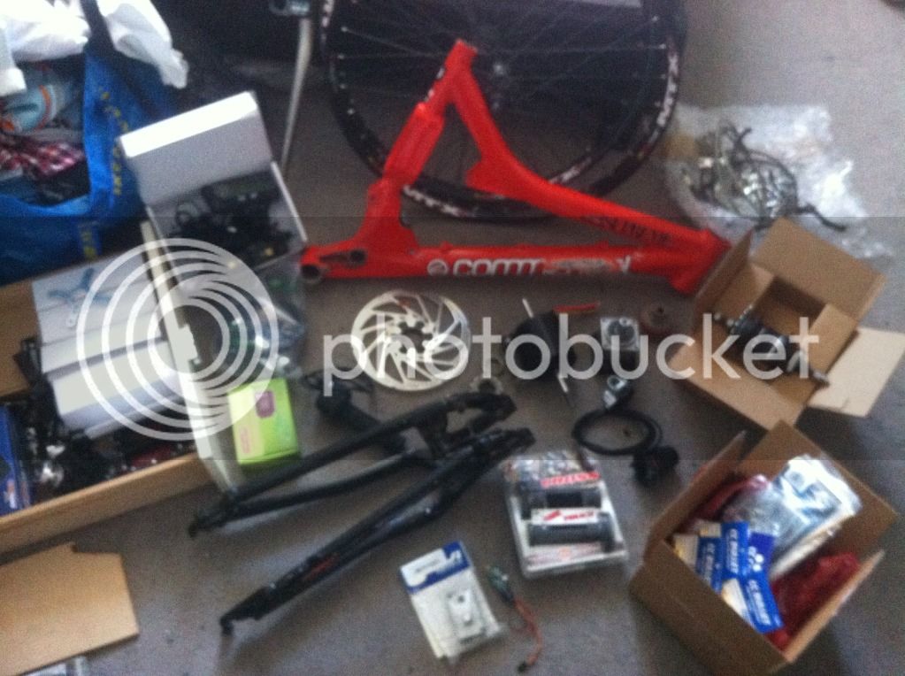
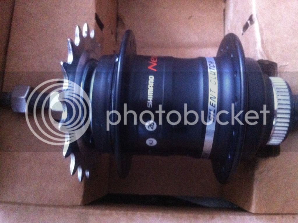
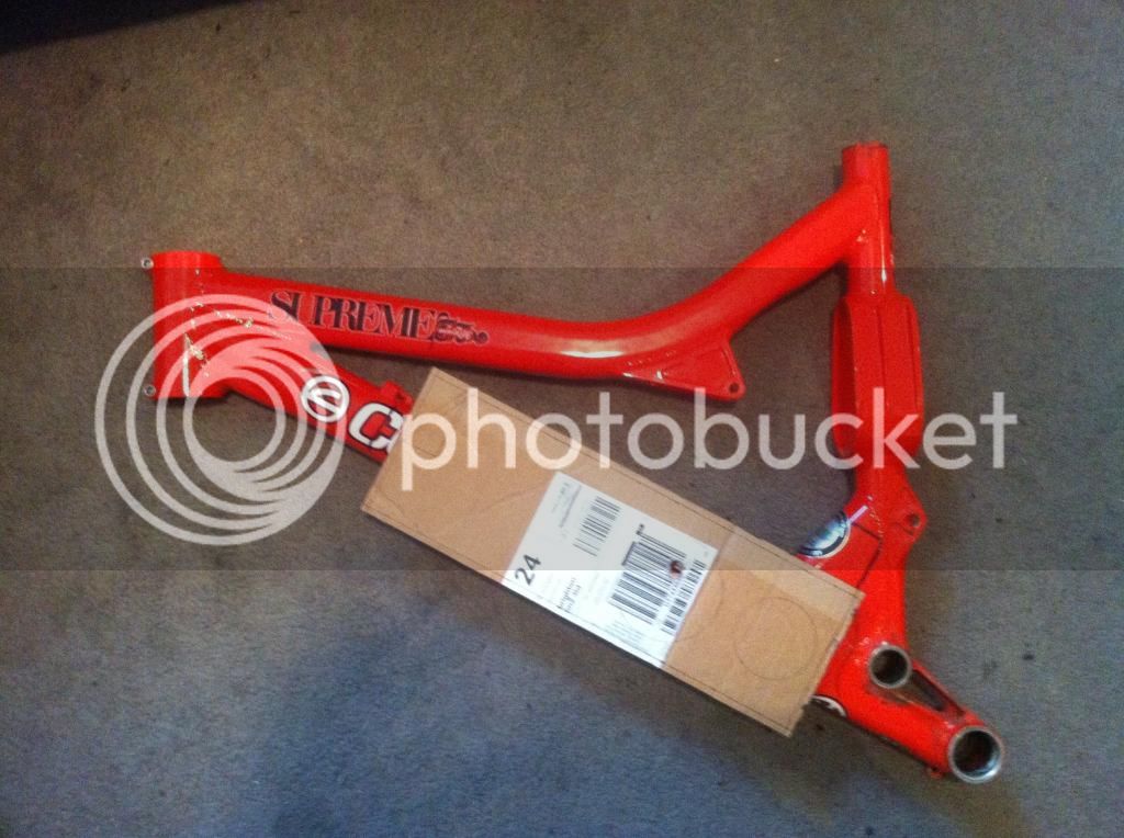
Thanks etard! I read about 50 pages of that thread and couldn't get anything useful, I will get back to it when I have more time! Today was a very good day for the Bike. After waiting 2 weeks for parts to go through customs/get held up in delivery networks, all of my parts seem to have come at once!! Here are a few pictures to keep this alive. I am hoping to have the bike built by the end of February!


Also, I have nearly finished the CAD drawings, will upload them later. This is basically what I'm thinking at the moment though. Cut a chunk out the downtube and TIG in a section of 120mm square, 5mm wall box section. My issue is that it intersects with the top tube. My batteries are 50mm x 50mm x 165mm, and I have 4. These are the largest part to package. The motor is 80mm in diameter, the gearbox in 60mm square. If anyone has any other ideas I will certainly take them on board. There needs to be some space around the motor for cooling, and some sort of chain tensioner. Another thing I'm worried about - having the gearbox close to the motor, and the walls of the box section quite tight, will this cause any issues with the magnets etc.? Anyway..


I could mount it lower, but I wanted to keep the lower line of the downtube ideally


I will upload the CAD later, looking forward to hearing your thoughts! I want to send the frame to the welder in a couple of days so the design needs to be finalised quickly!
 
A couple more questions :) I bought two castle creations parallel harnesses to save time making them (and I had a discount code!). They are 10awg wire, with deans ultra connectors. I was planning on cutting the deans connectors off and using castle 5.5mm bullets. Is 10awg thick enough to connect up all my packs? It's worrying me that the packs have 8awg coming out of them. I wanted to use the 5.5mm bullets to connect the batteries to the ESC, and the ESC to the motor too, but they seem a little small. Will this all be alright?
 
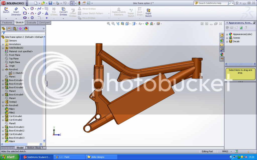
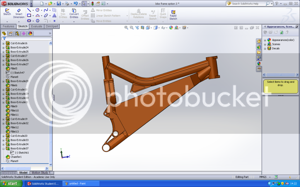
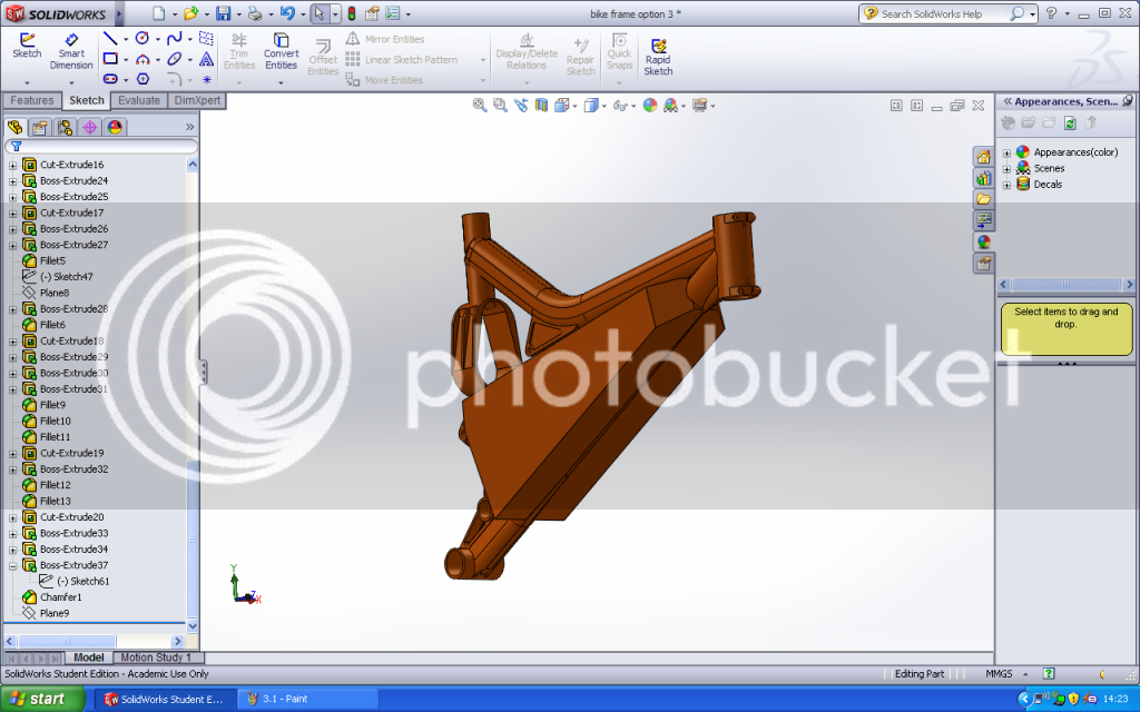
This is my frame modelled in SolidWorks


I was originally thinking this:


Although it interferes with the top tube. This moves it down (although still very close), but looks worse and gives less ground clearance:


And this is the ultimate design, although it's a lot more welding (I was going to use square box for the other designs):


So it seems it not going to be such a simple analysis. I need to speak to the guy who will be welding it to see if he can do the final design. I will keep this updated and also test it in Solidworks, but I would really like to be able to include some calculations and actually show some thought went into it!
 
I don't like it (especially not the boxy one!). Sorry if I missed it, but are you welding aluminum box to aluminium frame? This is basicly copying Timma's design but not as well intregrated into the frame. Have you thought about fitting 4 batteries in the triangle and 4-6 on top of the top tube with a skeleton clamped on the frame with 2 side panels that can be unscrewed for access to the guts? This could be done without welding, but could possibly require machining the mounts. I don't know if you are trying to preserve the look of a bicycle, but your boxy enclosure is ruining the look as is anyway IMHO. The shaped box is much better, definately worth the extra effort.

Also, if you build your enclosure over the top tube, you can put all your switches and monitoring equipment there.

Timma's build:

http://endless-sphere.com/forums/viewtopic.php?f=6&t=34719

Just giving my opinion, it might not align with your intentions, so take it with a grain of salt.
 
etard, no problem! I like to hear peoples views. I know all options are quite ugly, and the bottom one is by far the best! The reason is that the frame is actually very very compact. I can only just squeeze 4 batteries (in a square shape) and my motor and gearbox in the boxy design, and it's still very tight. I also want a lot of protection for the batteries, and my motor and gearbox can be easily mounted within the box. I couldn't fit my motor, gearbox, and batteries within the triangle - look where the shock goes. I could mount them on top of the top tube, but that's not really great for weight distribution, and they still wouldn't really fit well. Any more ideas/input welcome before it's too late!
 
the bottom design looks good & stronger..
the top one I wonder if the structural integrity is diminished..
but hey if it works then who really cares what it looks like anyways..
8)
 
Well I've spoken to the welder and he's said the bottom design is no problem as long as I cut the plates to size and prepare the frame :) so now I just need to decide what thickness plate to make it out of, the grade of aluminium to use, where to add ribs or strengthening, and how to fit the motor/gearbox :lol:
 
That solidworks model looks nice! How did you made that, so that it's still accurate to the real one? (Or did you downloaded it somewhere?)
 
I would like to heat treat it, but I don't have any equipment to do so? Do you think this is absolutely essential? Do most welding places have the equipment to heat treat aluminium? Byte, not so technical, but I drew around the frame onto a piece of card then measured all the dimensions. It's as accurate as I can get without a coordinate measuring machine or something (and is perfectly accurate to within a few mm). Just struggling on my positioning of parts within the box section. Space is still very tight. I want to keep the batteries as the largest dimension, and chains as short as possible, but it's proving difficult. I really want to keep it to 100mm wide though. Back to the drawing board :lol:
 
Finally started making progress on this again today after exams. Hoping it progresses very quickly from now! Drilled and bored the clutch to fit on the gearbox output shaft, milled the edges and 10mm off the back of the gearbox, made up some parallel harnesses with bullet connectors for my batteries, and pulled the motor apart and removed the skirt bearing. Also started to look at the wiring but got stuck with the shunt. Think I'm actually going to use the external shunt (didn't realise how large it was until it arrived!).


Ready to re-terminate in wye:


Skirt bearing and massive shunt!:


Next on the to-do list:

1. Re-terminate the motor in Wye configuration (any help/tips please!)
2. Take 10mm off the motor can where the skirt bearing was (tried to do today but needed a different chuck in the lathe)
3. Mill the motor mount down 3mm
4. Somehow mount a sprocket to the motor
5. Somehow mount a sprocket to the gearbox input
6. Get the motor running on the bench (at last!)

The frame material has been ordered and should be here monday. I need to CNC the side panels, cut the other panels to correct shape then straight to the welder to be TIG'd up :twisted:
 
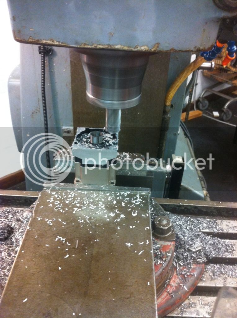
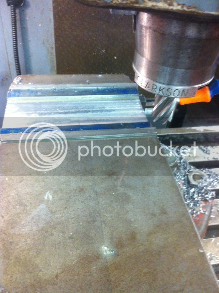
Today's progress.. milled the motor can down about 8mm, and the mount about 3mm-4mm. Also milled 5mm down to re-install the bearing in the mount. Ordered the ring terminals to connect up my massive external shunt. Hopefully the motor will be back together and running by the end of the week with the shunt etc. all working :)


Took about 5mm off the sides and 10-12mm off the end of the gearbox:

 
Slightly more progress today. Decided on the massive shunt so I cut the CA connector off the moulded shunt, extended all the wires, soldered the red to the controller positive, the green and yellow and added a black to the controller, and then added ring terminals for the shunt to the remaining wires. Also opened up the Cycle Analyst, removed the 5v lead for lighting, and replaced the lead with my throttle lead then wired it up with a 470ohm resistor. If someone could confirm this is correct that would be great! This is the first time I've ever soldered, I didn't realise how easy it is! Love it.


Hello Sellik

Nice improvements....
About the frame, what is exactly the alloy the frame is made by? it is a 2008 frame? you know the thickness of the tubing? maybe is made by 6061 but the later models are made by 7000 series...these are really important questions to know before to weld it in any way. 7000 serie is stronger but 6061 is way better to be welded, but there, the heat treatment would be even more crucial....
Cannot wait to see this gearbox running....as the whole bike!!! :)
 
Since you have access to a machine shop, I am wondering if making up the end caps to your box and bonding them on the end of the downtube after you cut out the section is a viable option to welding. You could then make up a structural component in the middle much like Panurge and his company has done without welding.

If your professors know anything about bicycles, they will also know that messing with the heat treatment of the frame is best left to the pros (the Taiwanese).
 
Thanks guys. The frame is 7005. My added section is 7020 which was very hard to obtain, hence the delay! However, it is arriving on monday. The downtube is 2mm thick. The added section is also 2mm thick. Thanks for the input etard, I did think about bonding, but I understand aluminium is difficult to bond well. Also, the downtube is in tension. Since the added section needs to be welded anyway, I might as well weld the lot. Also, 7xxx series aluminium is very easy to heat treat post welding. 6061 would have been an entirely different situation. This week should be good for lots of updates! However, I asked the technician at uni to solder in my cap-pack and he's done it at a very odd angle! Is this likely to cause any issues? Picture below!

 
Nice that the frame is 7005, it would make things a lot better....
About bonding, I agree to not perform it in this situation. Even if some of our frames is bonded in some places, we never managed to bond a downtube :). A failed bond should never lead to a frame in 2 parts..IMHO..For instance, we used to create composites sections (CF pipes bonded to ergal CNC end-billets) that are than mechanically coupled with the true structural frame, or pipes into pipes (seat-post into seat-tube rings), so that the bonded parts are mechanically constrained against the major forces they are subjected to...
About the CapPack soldering....It is really hard to solder it centered close to the ESC....After a pair of failures trying by myself, I had to ask a friend of mine who's a pro....he has loaned me a special soldering station with 2 output one of which acted by a pedal and a micro-clamp top tool for the 'columnes' of the cappack and told me to make some sort of minijig fixture, this definitively worked perfectly.... So, first you obviously need to fill with the soldering alloy the small CapPack terminal and presolder the peeled wire section, than fix everything into the jig so that there's a pressure between the 2 parts, and proceed with the 2 irons (one clamped to the column and the other by hand to the top).
Note that my wire goes from the esc to the CapPack with a 90° angle and it has 4000Km this way....so the process has been very strong....
A good approach is to wait to know exactly how your ESC will be placed...so you can solder it in a convenient way.
You donot need the cappack for bench tests without serious load...the moulded shunt and the HV as stock, are more than enough....
I remember MotoMoto has made it with a T junction for one of the wires so that the CapPack resulted a bit out-centered.
 
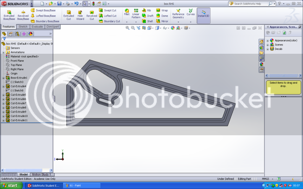
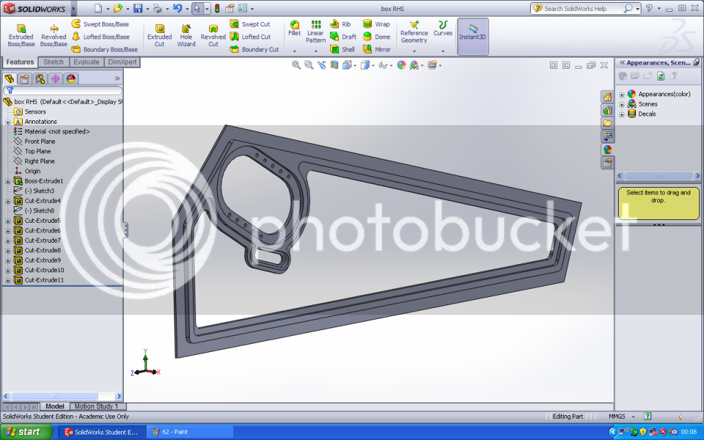
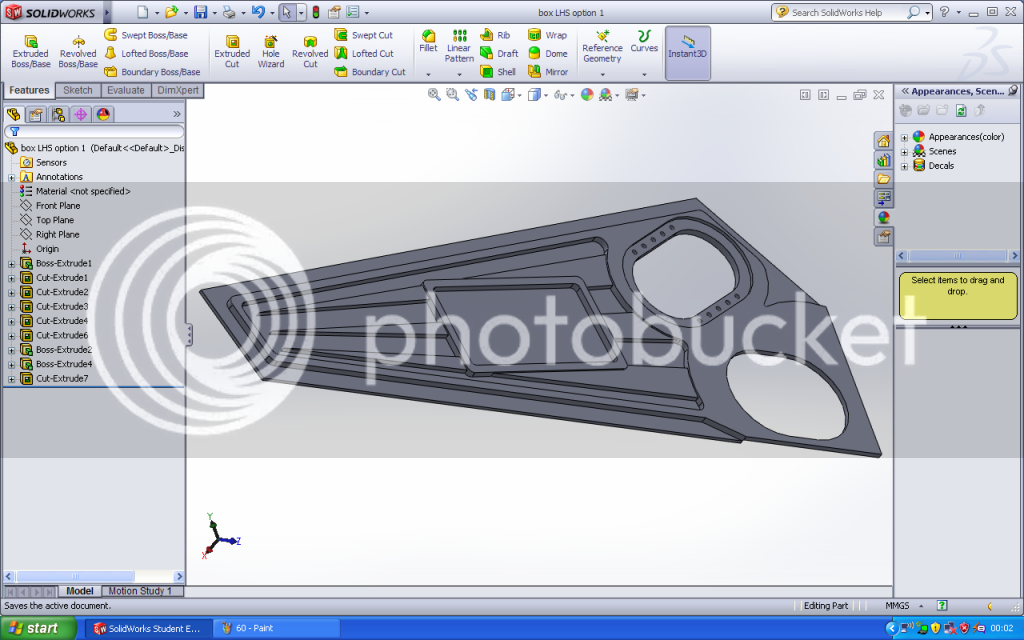
It makes it easier apart from sourcing material, which came today and is the wrong size!! Hopefully sorted now, just got to wait for postage again! I'm pleased that you agree about the bonding, nice to have your input, your DH frames are beautiful! Also reassuring input on the Cappack :) Final design for the frame sides is shown below. Any input would be very greatly appreciated, however, I'm hoping they will be machined tomorrow, so be quick :lol: It's 6mm thick plate, milled down to 2mm thick at the edges, and 3mm for the side cover recess.

Right hand side (large hole is for side cover, smaller hole is motor mount, and even smaller is tensioner):


Left hand side:


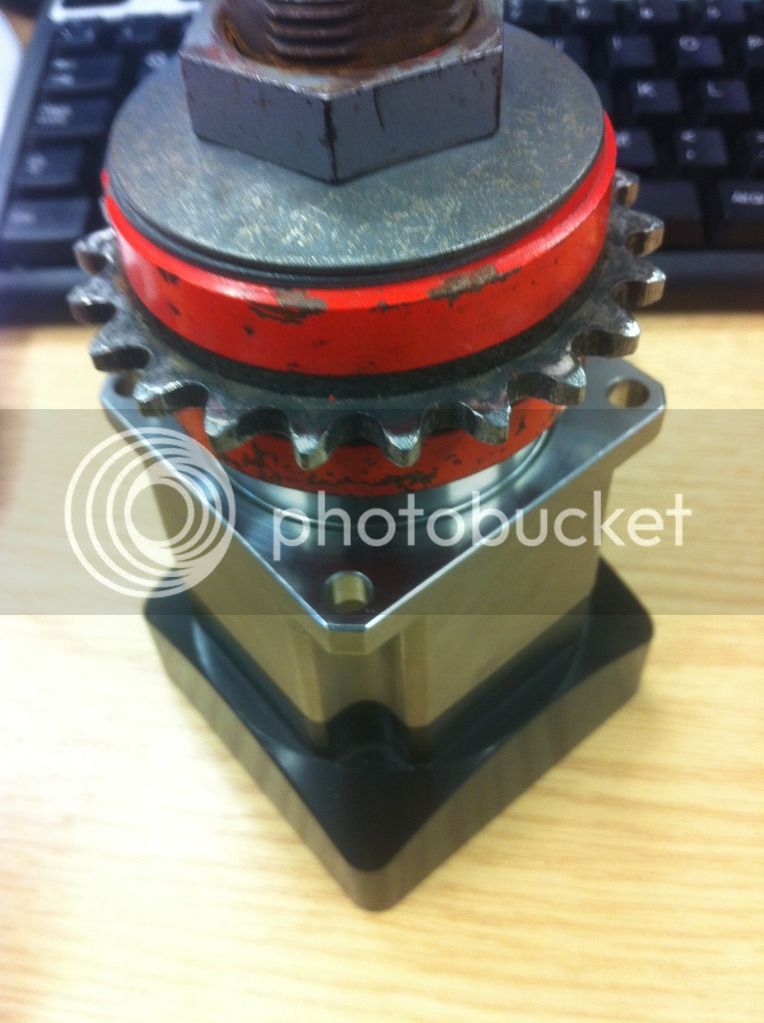
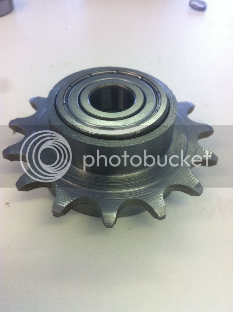
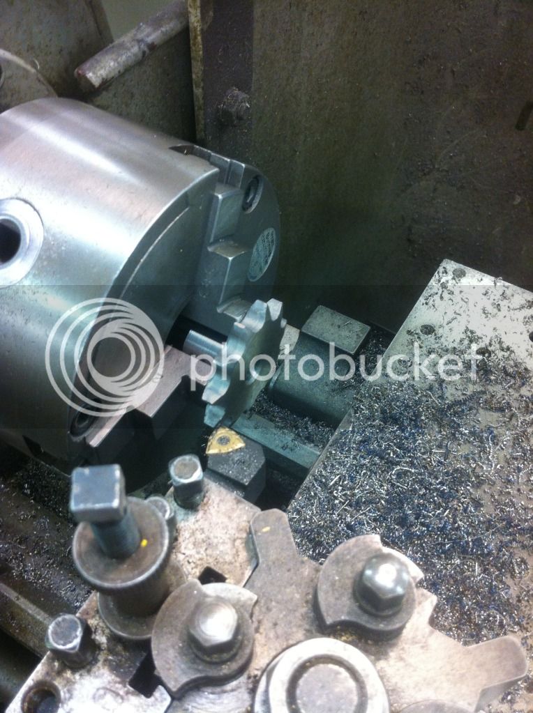
Little more done today while I wait for the frame parts to be CNC'd. Made the freewheel to be driven by the gearbox and mounted on the jackshaft. This is a steel sprocket, with csk12 sprag clutch/one way bearing, and an SKF bearing in there too. Hopefully it will hold up a bit better than the cheap freewheels! Started with a large duplex sprocket:


Turned one of the gears off:


Turned down the outer diameter, then drilled and bored 20mm deep for the bearings. Also turned a small amount off each side of the remaining gear, and added a chamfer back on afterwards, so it will work with bmx chain

 
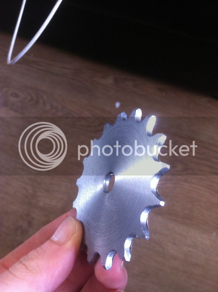
Very small update, still waiting for the sides to be cut. Milled down my sprocket from 6mm wide to 3mm wide so I can use it with bmx chain. This doesn't look like much, but it was very difficult to mount in the lathe. Also had to take the chamfer off both sides, then put a smaller one back on afterwards. These sprockets are also very hard steel, which is good because they should hold up well, but they are difficult to machine! Just the motor sprocket and gearbox input sprocket to go now.


Also found out that the uni has a motor dynamometer! Which is great news. As soon as my motor is back together I will be testing it (hopefully next week). I want to produce a graph with the current, efficiency, power, and torque of my motor
 
Ahaa, that boring bar was only used to bore about 2mm but it did blunt it! Some more slow progress today. Turning the motor output and gearbox input sprockets:


Started on the gearbox mounts:


Still working on getting my motor back together (with massive help from Gwhy!), everything always seems to take longer than expected.
 
Back
Top