fechter said:
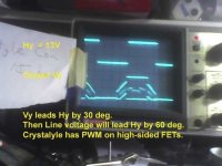
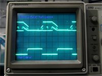
I took my standard test motor and gave it enough voltage to hit 325 Hz and the jitter still happened. My test motor is very small, neutrally timed, wye configured. At full speed it draws about 0.25 amps no load. When the jitter starts, the current jumps to over 1 amp.
BTW, the Shenzhen controller has what appear to be connection points for a PIC in-system programmer interface. The MCU appears to be something like a PIC16F72.
Fechter discovered there is an "critical" frequency of about 325 Hz for this Shenzhen controller which uses some standard "digital MCU" board. He has done extensive tests and reported his down-to-earth findings.
Shenzhen controller behaves well for power frequency less than the critical frequency. But it will behave very abnormally if it is only very slighlty above this critical frequency. The current could increase abnormally and damage the motor and the controller it
We have tried to find out "WHY? ".
Up to now some possible causes and comments are:
1) The analog delay in the LP filter at the Hall signal input. But the abnormal increase in current for a slight increase in frequency is very sudden. So it does not seem to be the cause beacuse the change in analog circuit is no so sudden.
2) The digital delay in processing in the MCU. Don't think this is the cause because the MCU speed is very, very high.
3) There is a pre-program for overspeed in the MCU. Don't think this simple MCU has such program. Even if it has, it should not cause the sudden abnormally increase of the current, but should reduce the current gradually when overspeed.
I try very to recall my knowlege of digital signal processing, filtering and signal representation to see if there is another possible cause.
One other possible cause could be due to the limitation of the digital representation of an analog signal when the analog signal exceeds the limit value.
Let me illustrate by using an 2-bit word to represent 4 levels of analog signal (say 0 to 3 Hz).
00 = 0
01 = 1
10 = 2
11 = 3
The limit frequency is 3 Hz
What will be the digital representation if the frequency is 4 Hz (1 Hz about the limit 3Hz)?
In 2-bit math:
11 + 01 = 00
Now it becomes 0 Hz for the MCU, the MCU will give a "wrong" output and cause the abnormal change.
Assume that this controller uses an 16 bit word to represent 65536 levels of frequency (0 to 65535).
Level 0 => 0 Hz
Level 65535 is used to represent the limit frequency (say, the critical frequency at 325 Hz).
Each level = 325 /65536 = 0.005 Hz.
The digital representation will be completely "wrong" if the frequency is slightly above the limit frequrncy.
Apparently the board of this controller was designed on the understanding that the power frequency will never exceed the critical frequency (about 325 Hz) which is valid for gearless hub motors.

 ). Don is Mechanical Engineer. Been in the motor business for decades. He lives in Oklahoma (I think) but his wife is Chinese. He travels to China a lot. He's been importing electric starters from China for like EVER. Lives there too I think. Don got his first gas-bike kit many moons ago and has been hooked on powering bicycles ever since. His motors have good rep in Asia. I think he selling most there right now.